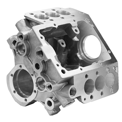









Custom Housings Machining
Custom housings machining with bearing bores to H7, 0.01 mm coaxiality and walls down to 0.8 mm. Standard tolerance ±0.005 mm, no MOQ, prototypes in 3–5 days.
-
±0.005 mm
Standard Tolerance
-
H7
Bearing Bores
-
3–5 days
Prototype Delivery
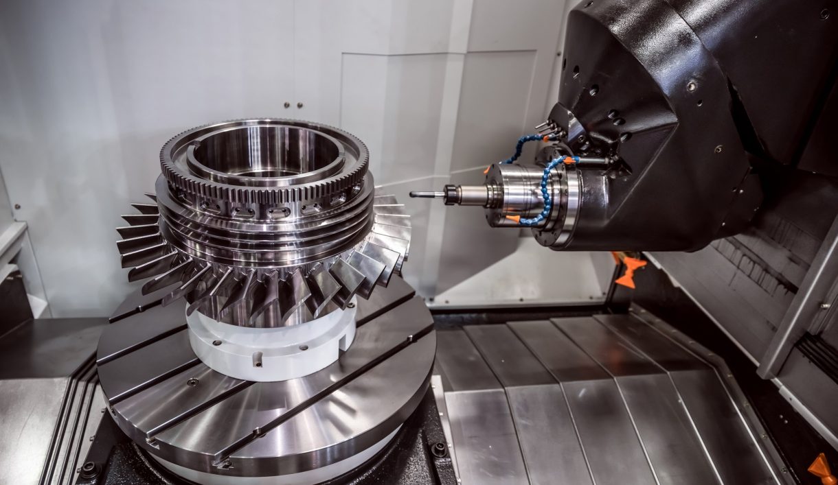

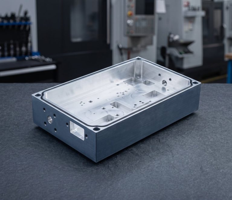
CNC Machined Housing and Enclosure Work
DEK machines motor, gearbox, actuator, sensor, camera and RF housings plus billet electronics enclosures, in aluminum, 304/316 stainless, cast iron and engineering plastics. Housings are one of the largest families in our custom CNC machined parts catalogue.
A housing must locate bearings or boards, seal and shed heat, so we hold gasket faces flat to 0.02 mm. For thin-wall boxes or profiles at volume, see aluminum box fabrication; the guide to machined enclosures gives a broader overview.
Housing and Enclosure Types We Machine
Motor, gearbox, electronics, RF, sensor and bearing housings, milled from aluminum, stainless, cast iron or plastic billet.
-
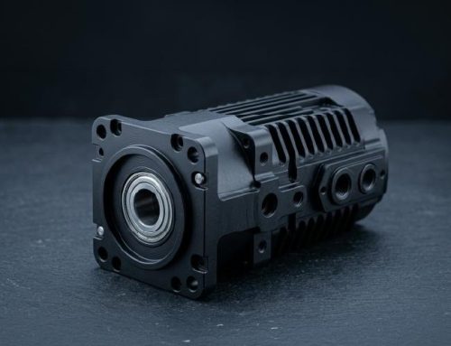 Motor Housings & End BellsBearing bores, cooling fins and stator seats for electric motors.
-
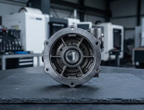 Gearbox & Actuator HousingsGearbox, actuator and joint housings with multiple coaxial bores.
-
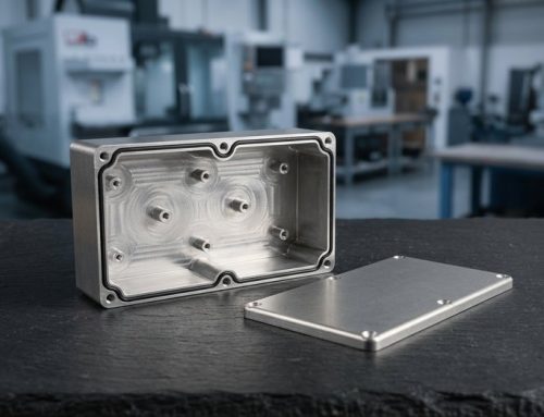 Electronics EnclosuresBillet boxes with lids, O-ring grooves, cutouts and PCB standoffs.
-
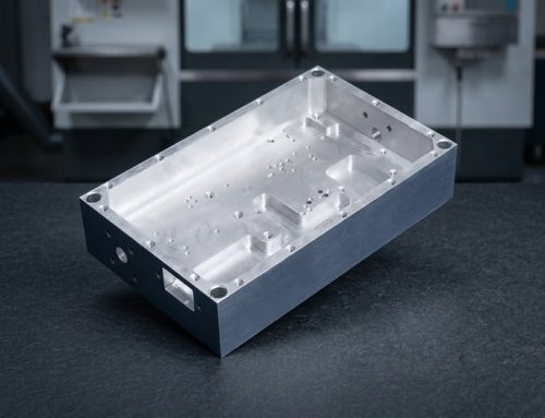 RF & Cavity-Filter HousingsRF and microwave housings with tight cavities and plated surfaces.
-
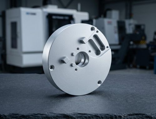 Sensor & Camera HousingsSensor, camera and lidar housings with optical bores, lens seats.
-
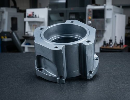 Bearing Housings, Valve BodiesBearing housings, pillow blocks and valve bodies in steel or iron.


Housing Materials, Processes & Tolerances
Material choice, machining route, tolerances and finishes for billet housings and enclosures, all from one engineer-reviewed workflow.
Design Tips for Machined Housings
Five drawing choices that cut cycle time and keep bores, seals and fins within tolerance on custom housings.
-

Generous Internal Corners
Keep corner radii at 3 mm or larger on deep pockets; a 1 mm corner in a 60 mm cavity forces a slow, chattering cutter.
-

Bores From One Side
Machine all bearing bores from one side, or add a dowel pair so both halves can be line-bored as an assembly.
-

O-Ring Groove Placement
Put O-ring grooves on the flat face, not the wall, and give the groove a 0.2 mm radius at the bottom.
-

Cooling Fin Proportions
Keep cooling fins at 2 mm minimum thickness and no taller than 4× their thickness to avoid chatter.
-

Stock for Hard Anodizing
Leave 1.5 mm of stock on sealing faces if hard anodized; Type III coating adds 25–50 µm per surface.
What to Call Out on Your Drawing
-
Bearing Bores
State bore fit (H7 standard, H6 on request) and coaxiality between bores; 0.01 mm is achievable on a shared datum.
-
Sealing Faces
Mark gasket faces and O-ring grooves: flatness 0.02 mm, groove width and depth ±0.02 mm, Ra 0.4 µm on sealing faces.
-
Finish and Masking
Specify anodizing type or chem film, and which surfaces must stay conductive for EMI grounding.
-
Threads and Ports
List thread sizes (M2–M20 6H) and NPT/BSPP ports for cable glands and fittings, plus the quantity you need.
Applications & Industries
Joint and drive housings for robotics, enclosures for electronics and telecom, motor housings for new energy drives, sealed medical device housings.
-

Aerospace
-

Medical
-

Automotive
-

Robotics
-

Semiconductor
-

Electronic
-

Telecom
-

Drone & UAV
-

Energy
-

Oil & Gas
-

Marine
-

Industrial Equipment
-

Construction
-

Agriculture
-

Consumer Products
-

Military & Defense
-

Mining
-
 AerospaceNon-flight-critical brackets, cabin hardware and fittings under AS9100D, in 7075 aluminum, Ti-6Al-4V and Inconel 718, with FAI.Learn More
-
 MedicalInstrument shafts, handles and cannulas in 316L stainless, titanium and PEEK under ISO 13485, with lot traceability as standard.Learn More
-
 AutomotivePrototype and low-to-mid-volume sensor housings, valve bodies and shafts in aluminum, 4140 and 4340 alloy steel, stainless and brass.Learn More
-
 RoboticsJoint housings, harmonic drive flanges and gripper fingers in aluminum and hardened steel, with 5-axis milling in one setup.Learn More
-
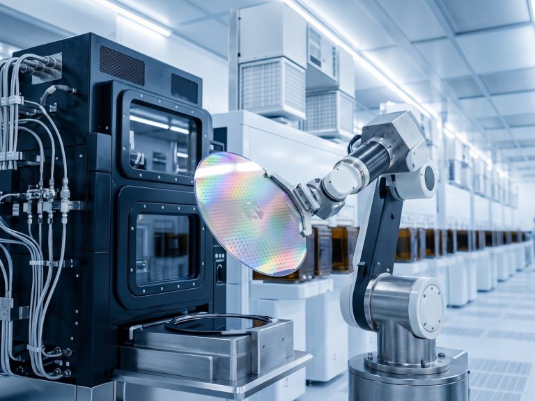 SemiconductorChamber components, wafer handling fixtures and vacuum flanges in 6061 aluminum, 316L, PEEK and Kovar, with burr-free edges.Learn More
-
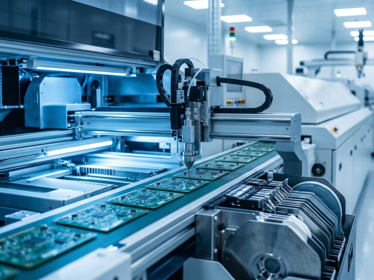 ElectronicConnector bodies, heat sinks, RF shields and precision pins in aluminum, brass and copper, held to ±0.01 mm on contact features.Learn More
-
 TelecomWaveguide components, filter housings and RF enclosures in aluminum and copper alloys, with silver or nickel plating for conductivity.Learn More
-
 Drone & UAVMotor mounts, gimbal frames and landing gear fittings in 7075 aluminum, titanium and magnesium to cut weight without losing stiffness.Learn More
-
 EnergyBattery end plates, busbars, inverter housings and fuel-cell fittings in aluminum, copper and stainless, machined flat and burr-free.Learn More
-
 Oil & GasValve components, manifold blocks, downhole tool parts and flanges in 4140, 17-4 PH, duplex 2205 and Inconel, with hardness specs.Learn More
-
 MarinePropeller shafts, pump parts and deck hardware in 316 stainless, bronze and aluminum bronze, chosen first for corrosion resistance.Learn More
-
 Industrial EquipmentGripper plates, linear guide mounts, cam followers and machine frames in aluminum and steel, with fixtures kept on file for repeats.Learn More
-
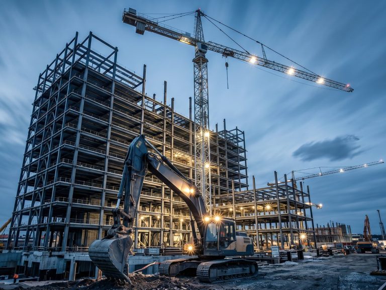 ConstructionStructural brackets, anchoring hardware and hydraulic fittings in mild steel, alloy steel and aluminum, zinc plated or powder coated.Learn More
-
 AgricultureGearbox housings, shafts, sprayer nozzle bodies and sensor mounts in cast iron, steel and stainless for abrasion and moisture.Learn More
-
 Consumer ProductsKnobs, handles, enclosure parts and audio hardware where the machined surface shows, anodized, bead blasted or polished to sample.Learn More
-
 Military & DefenseOptical mounts, enclosures and accessory rails in aluminum, steel and titanium, with material certification and FAI reports.Learn More
-
 MiningWear plates, bushings, crusher components and hydraulic fittings in hardened alloy steel, bronze and stainless for dust and vibration.Learn More
Why DEK for Custom Enclosures Machining
Housings expose every weakness in a shop: thin walls, deep pockets and bore alignment. Here is how we control them.
-

Drawing Review by Hand
Engineers review each drawing before quoting and flag any pocket depth or wall that will not hold tolerance.
-

CMM-Verified Bores
Bearing bores are verified on CMM against H7 fits and 0.01 mm coaxiality before parts leave the shop.
-

Flat Sealing Faces
Sealing faces are checked on a surface plate to 0.02 mm flatness so gaskets and O-rings seal first time.
-

Thin Walls Held
Walls down to 0.8 mm in aluminum, 1.5 mm on pockets deeper than 50 mm, with pockets up to 6× cutter diameter.

Reports Before Shipment
Photos and inspection reports are sent before every shipment, under ISO 9001:2015, ISO 13485 and AS9100D certified quality systems, so you approve housings before they travel.
Certified Quality for Every Housing
Housings are machined and inspected under ISO 9001:2015, ISO 13485 and AS9100D.
-
 AS9100D
Aerospace Quality Management System
-
 ISO 9001:2015
Quality Management Standard
-
 ISO 13485
Medical Devices Quality Management
Housing Materials and Surface Finishes
Aluminum, stainless, cast iron, magnesium and plastics, paired with finishes applied to the housings we machine.
Surface Finishes
Engineering Plastics
Need another alloy or finish? Ask our engineers.
All MaterialsFrequently Asked Questions
Answers on enclosure routes, motor housing tolerances and finishing.
Get a Quote for Custom Housings Machining
Send a STEP file plus drawing showing bearing bores, sealing faces, finish and quantity. Every quote is reviewed by an engineer.
- Engineer-reviewed quote within 6 hours
- Complex 5-axis housings: up to 3 days
- No MOQ, prototypes in 3–5 days
- Critical dimensions held to ±0.005 mm

Ready to Scale Your Project?
Get started with a stable process and controlled quality. Let's discuss your project.