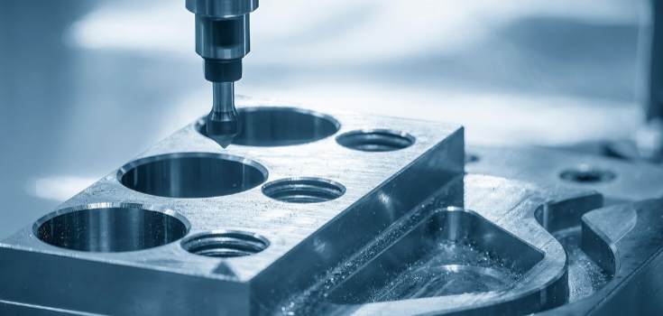
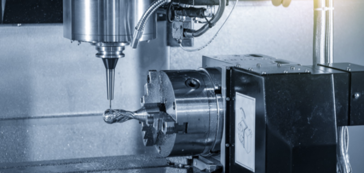
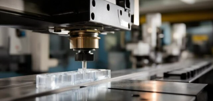
If you intend to work on a machining project involving precise angled cuts, understanding angular milling is key. This milling technique helps ensure accurate precision and efficiency, and can also help you achieve complex geometries and designs that cannot be done with regular milling.
In this post, you will explore the processes involved, types of angle milling cutters, advantages of angular milling, and so on.
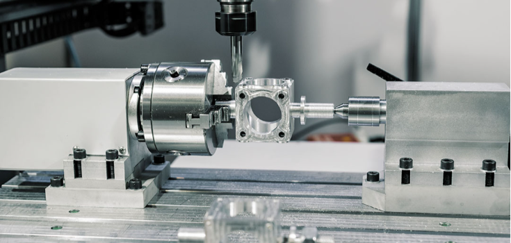
What is Angular Milling?
This is a unique milling method used in cutting materials at specific angles, excluding 90 degrees, until a desired design, shape, or geometry is achieved.
This machining technique uses specialized procedures to generate angled features like chamfers, notches, bevelled edges, V-shaped grooves, etc.
Unlike the conventional milling type that is used to create basic flat surfaces, angular milling is suitable for manufacturing complex angled grooves and finishes.
Types of Angle Milling Cutters
Below are two types of angle milling cutters to note.
Single-Angle Milling Cutter
Single-angle milling cutting tools are used for milling operations with one angled face.
They are usually designed as 30, 45, or 60 degrees, although you might find other custom angles depending on your needs. Single-angle cutters are used in chamfering, bevelling, and machining of one-sided grooves and edges.
Double-Angle Milling Cutter
These are used for complex machining projects involving two angled milling faces. Usually, they have two angled cutting features that enable them to create V-shaped grooves on a workpiece.
They are available in 45, 60, and 90 degrees. Because of the advanced multiple-angled profiles that they possess, they help improve work efficiency and enhance work speed since there’s no need for frequent repositioning and adjustments.
How Does Angular Milling Differ from Regular Milling?
Angular milling is different from the regular or conventional milling technique in the following ways.
Cutting Geometry
Regular milling is usually used to create flat surfaces with the milling tools moving perpendicular or parallel to the workpiece. In angular milling, machining operations are carried out at specific angles to form grooves and edges.
Cutting Tools
In a regular milling operation, face mill and end mill tools are used, while in angular machining, unique single and double-angled cutter tools are applied to achieve adequate precision and functionality in the production process.
Applications
While regular milling is suitable for machining components with basic features and geometries like slots, blocks, etc, angular milling is suitable for creating parts with detailed precision like chamfers and other intricate angled parts.
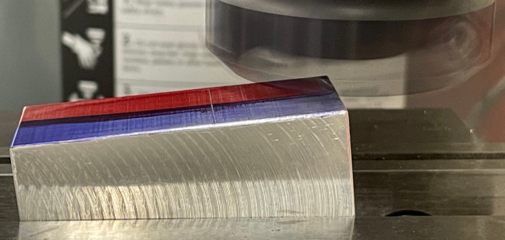
Angle Milling Process
Here is a step-by-step process of angular milling you can follow:
Planning and Preparation Process
This is the first step and it involves preparing the materials and cutters, designing drawings and blueprints, and so on.
Here, you will need to decide on the workpiece angle, whether it's 30, 45, or 60 degrees, or if a custom degree is required. Doing this will help you select the accurate cutter.
Beyond that, you need to choose either a single or double cutter based on the project you’re working on. The material of the cutter also matters; for example, carbide can handle many metallic parts with moderate to high tensile strength.
Milling Machine Set Up
At this stage, you will set up the milling machine for the angular machining process. You would need to check if the machine comes with a tilt head feature.
After that, you can use a measuring tool like a dial indicator to see if the tilt is correct and it aligns with the milling requirements.
In situations where the machine doesn’t have a tilt feature, you can generate the angles needed by providing firmly held fixtures like rotary tables to support the milling process.
Once this is done, inspect the machine set-up for firmness and alignment. With this, you can achieve the required precision, enhance tool life, and work efficiently.
Workpiece Set Up
Since the angular machining process generates a lot of vibrations and forces, you should ensure that the workpiece is securely fixed.
Using specialized fixtures or sine vises created for angular milling is vital to ensure a stable workpiece setup. Once the workpiece is secured, you can use a measuring tool to check for alignment again.
Machining of the Angle
The next process is to begin the actual machining operations. Once you start milling the angle, you should begin with stable feed rates and spindle speeds.
This would help you reduce tool chatter and prevent deviations that might affect the finishing and precision level.
You would also need to use coolant to reduce heat buildup. Testing the machining process ahead of time for speed and feeds also helps ensure that you get the correct parameters for the milling operation.
Quality Control

Lastly, go through a thorough inspection to ensure that the machining outputs meet the desired project requirements.
This involves checking if the precision level, surface finishing, dimensions, tolerances, etc., meet the expected specifications. While final quality control is crucial, inspecting for those parameters during the machining process is good.
Commonly Used Materials for Angle Milling
Many metallic materials are used in angular milling operations. Each of them has its own properties that make it compatible with such a machining process. Below are some of the materials and the parameters to know about them.
| Material | Hardness | Tensile Strength | Machinability (% of B1112) | Applications |
| Steel (Carbon and Alloy) | 120-250 | 400-1500 | 50-70% | Essential in structural engineering, machining parts and components. |
| Stainless steel | 150-600 | 480-2000 | 40-50% | Used in creating medical equipment and food processing components. |
| Aluminum Alloys | 25-150 | 90-570 | 150-300% | Vital in designing aerospace and automotive parts and electronic components. |
| Brass | 55-100 | 200-550 | 100-150% | Used in creating aesthetic equipment, plumbing parts, and musical instruments. |
| Titanium Alloys | 180-420 | 650-1400 | 20-30% | Important in making aerospace and automotive parts and biomedical equipment. |
| Copper | 35-110 | 200-400 | 20-100% | Essential in producing electrical and plumbing parts. |
| Nickel Alloys | 150-500 | 600-1400 | 10-40% | Used in manufacturing chemical processing equipment and marine engineering components. |
Advantages of Angular Milling
Here are some of the benefits of angular milling operations:
Enhanced Efficiency
Angular machining allows multiple angled features to be generated on a workpiece just in a single operation. This way, you can maximize time and labor while also getting more output.
High Precision
With angular milling, you can get components with adequate precision. The milling methods help ensure that the necessary angles are reached during manufacturing, thereby eliminating deviations while generating parts that meet required specifications and functions.
This makes it valuable in creating aerospace, medical, and sports components.
Cost Effective

You can also effectively maximize material usage with this technique. In angular milling, only the necessary parts are worked on, thereby preventing material wastage.
Perfect Surface Finish
Angular milling gives a smooth finishing touch. With this, you don’t need a final finishing process and can, therefore, save more time, labour, and cost.
Improved Designs and Functions
Without angular milling, creating some components would not be possible. Complex and intricate geometries are designed using this technique.
With this, it becomes easier to generate parts with specific features, aesthetics, functions, and so on, thereby leading to more customer satisfaction.
Limitations of Angle Milling
Set Up Complexity
Setting up an angular milling cutter together with the workpiece and machine takes more time and expertise. Moreover, you must align the setup properly for it to work. Without this, there are more chances for errors, which will cost you more time and effort.
Tool Wear Out
Tool wearout occurs more in this technique because of the angled surfaces. The cutting tools constantly work on the material at specific angles, leading to the wear out of the tool. With this, you will need to replace the cutter more often.
Machine Requirement
Many of the regular milling machines are not suitable for angular milling. To be able to carry out angular machining, you might need to invest in advanced CNC machines.
Common Applications of Angular Milling
Chamfering and Bevelling: Valuable in creating chamfers, preventing components from edge damage, and enhancing fitment.
V-groove Milling: Useful in generating V-shaped grooves in machining components and decorative parts.
Thread Milling: Important in generating threads on screws, bolts and other fasteners.
Dovetail Slot Creation: Useful in machinery and structural engineering to design interlocking joints and dovetail slides.
Serration and Knurling: Used in creating features to enhance fastening or gripping.
Tapered Surface Machining: Valuable in designing shafts, pins, etc, which are useful in structural engineering.
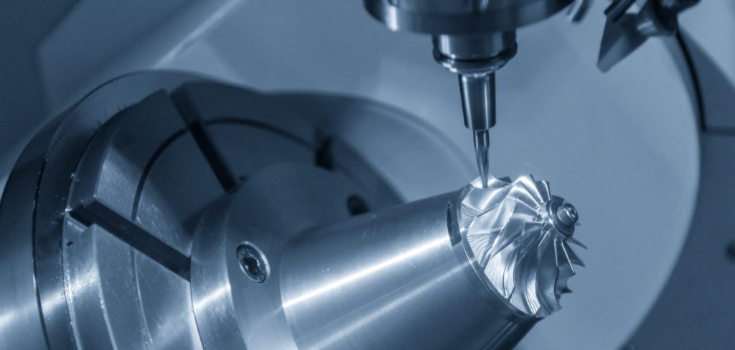
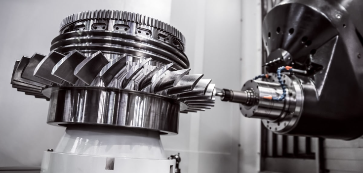
Complex Angular Components: Used in designing aerospace parts like turbine blades that need adequate angle precision.
Fixture and Tooling Parts: Important in making jigs and fixtures used as support in the manufacturing process.
Helical Milling: Used in creating spiral and helical grooves in drills, cutting tools, etc.
Angular Slots: Valuable in creating slots in mechanical and structural components.
Tips for Angular Milling
Angular milling, as an advanced machining technique, requires some skills and expertise to carry out. The tips below will help in your next machining operations.
Select the Most Suitable Cutter
Depending on the components you want to create, you need to consider the type of cutter to use.
For basic angled machining operations like the creation of bevels and chamfers, single-angled cutters are good. However, for more advanced milling like V grooves, double-angled cutters are suitable.
Also, when working on tough materials like steel, carbide-coated cutters are the best since they can withstand extreme heat.
Create a Cooling Mechanism
When carrying out an angular milling operation, you should expect some heat generation. This can be managed by using a suitable coolant based on the materials you’re working with.
For hard materials like steel, use oil-water-based coolant. Less hard materials like aluminum only need mist coolants.
Test Milling Parameters
Testing milling parameters like speed and feed helps you determine the best balancing position for your machining operation.
This, in turn, helps you eliminate errors, improve precision and efficiency, and enhance tool lifetime. Usually, softer materials withstand high speed than harder ones.
Combine Cutters when Necessary
For more efficiency, you might need to combine cutters. For example, when milling a V groove, combining an end mill and an angled cutter will allow you to complete the operation without replacing tools.
Measure Angles and Inspect Surface Finishes

While angular milling ensures precision, you might also want to check the measured angles using an instrument like an angle gauge. Also, look out for the final finishing, if it’s smooth enough or needs improvements.
Provide Support for Holding Material
An angular machining set-up should be as rigid as possible. This milling technique causes a lot of vibration and tool breakage when care is not taken. So, you must provide custom rigid angular support to hold the workpiece while machining.
Conclusion
Angular milling remains a valuable technique for creating various angled industrial parts. With it, you can achieve components with consistent precision, finishing, aesthetics, and designs.
At DEK, we value accuracy and efficiency in our machining process. Over the years, we’ve equipped our workshop with sophisticated modern machines that meet every project's needs. Whether your project involves angular milling, CNC machining, or other procedures, we have the best team for the job.
CNC machining as a manufacturing procedure helps improve component precision, work efficiency, speed, etc. However, it comes in many versions, including 4-axis CNC machining vs 5-axis CNC machining. Deciding on which to use depends on some factors and their benefits.
In this guide, we will explore the two types, the pros and cons of each of them, when to use each, how to select the most suitable, and lots more.
What is 4-Axis CNC Machining?
This is a machining process that involves using a 4-axis machine to cut out material until a desired shape or design is formed.
Usually, it has 3 main axes together with an additional axis known as the A axis, which allows for proper rotational movement without any manual repositioning.
Unlike the 3-axis CNC machine that typically has X, Y, and Z axes, the A axis in 4-axis CNC makes it suitable for engraving and machining involving the vertical axis and on all four sides.
This process also allows for more accuracy and precision while minimizing costs and errors. Whether you are involved in milling activities consisting of hole drilling or cutting out, 4-axis CNC machines are more suitable.
Pros and Cons of 4-Axis CNC Machining
Pros
- Suitable for more intricate designs, shapes, and angles that 3-axis machines cannot handle.
- Helps increase efficiency since it doesn’t need manual repositioning.
- Allows for continuous operation, thereby improving work speed.
- Can be used for high-volume production.
- Suitable for several material types and sizes.
- Great work, precision, and accuracy.
Cons
- Requires a high cost of investment and setup.
- Relatively slower in operations compared to 5-axis
- Not suitable for machining large materials.
When Should You Use 4-Axis CNC Machining?
You should use 4-axis CNC machining when:
- Working on operations relating to curved surfaces and angles involving one axis.
- Machining parts that require higher tolerance and precision that cannot be handled by 3-axis machines.
- You want to generate high output or production volume.
- Working on parts with several sides and features
What is 5-Axis CNC Machining?
Just like the 4-axis CNC machine has an additional axis, 5-axis CNC machining involves two extra axes, which could be two out of the three A, B, or C axes. These 2 additional axes are also responsible for the rotational activities of the machine.
5-axis CNC machining allows for a more complex production process involving more geometries and angles, tolerance, and precision.
3+2-Axis CNC Machining
This is a type of 5-axis CNC machining, also known as positional 5-axis machining. In this type, the cutting equipment maintains a definite angle while the spindle moves around the two additional axes.
This way, the cutting tool is not always perpendicular to the part. Similarly, there is an indexed 3+2 machining form that allows the angle of the cutting tool to be changed manually during operations. It also has 2 rotational axes that work individually.
Simultaneous 5-Axis CNC Machining
Also known as continuous 5-axis machining. In this machining type, the cutting tool remains perpendicular to the part, allowing the machine to reach more intricate areas while providing quality surface finishes.
This method is slow compared to 3+2 axis machining; however, it can produce more complex curved designs and shapes
Pros and Cons of 5-Axis CNC Machining

Pros
- Can work on more complex geometries and angles.
- Operates at a higher speed in one setup.
- Adequate for higher precision and quality machining.
- Suitable for complex material while also working with less time.
- Can efficiently work on a contoured surface.
- Reduces tool wear out as much as possible.
Cons
- Require more purchase, set up, and maintenance costs
- Requires extra guidance and training to use.
- Might need more programming training due to the extra 2 axes present.
When to Choose 5-Axis CNC Machining?
You should use 5-axis CNC machining when:
- Machining involves higher production outputs.
- Working on more complex geometries, shapes, or designs.
- Higher precision is needed, for example, in the medical and aerospace sectors.
- Machining a workpiece with several sides and features on each of them.
What are the Differences Between 4-axis CNC Machining vs 5-axis CNC Machining?

Here are the differences between the 4-axis and 5-axis CNC machining you should know.
Difference in Axes
4-axis CNC machines have only one additional A axis, while 5-axis machines have two, which could be either of the A, B, or C axes.
Rotation in Axes
The 4-axis allows rotation only on the A axis, while the 5-axis allows rotation on two axes, either of the A, B, or C axes. This characteristic makes the 5-axis much more flexible in terms of the movement of the cutting tool.
Accuracy and Precision
While the CNC machining process is known for its accuracy and precision, 3-axis CNC machining might offer you less accuracy since it involves constant repositioning of the material.
4-axis and 5-axis machining, on the other hand, offers more precision since there is no manual repositioning.
This helps avoid deviations while also creating several designs on a material with just a single setup. However, the 5-axis provides more accuracy and precision compared to 4-axis CNC machining.
Lead Time
With 5-axis machining, less time is needed to complete operations, and so higher output can be generated while also improving efficiency. This is possible because of the multiple-cutting abilities that make machining much easier.
Flexibility
In terms of flexibility, 4-axis CNC machines usually have an additional axis on the X-axis. However, the 5-axis machines could have their extra axis on the XY and Z axes.
Cost

Generally, the 5-axis machines are much more expensive than the 4-axis. This is due to their advanced features and capabilities, enabling them to handle higher volume production, complex designs and so on.
Table Explaining the Differences Between 4 axis and 5 Axis CNC Machining
| Features | 4 Axis CNC Machining | 5 Axis CNC Machining |
| Flexibility | The additional A axis usually rotates around the X axis, which makes movement limited to a single direction. | The 2 additional axes rotate on the XY and Z axes; two out of the three. This allows for more rotation so that the material can be worked on from many sides. |
| Number of Axes | Has the basic XY and Z axes, together with the A axis. | It has the XYZ axes together with an extra 2 axes, which can be two out of the AB and C axes. |
| Volume of Production | Could handle high production but not as high as 5-axis | Can handle much higher volume production. |
| Cost | Relatively cheaper than 5-axis | Quite expensive compared to 4-axis machines |
| Application | Suitable for operations involving several sides, angles, and holes. | Best for advanced 3D machining requiring more accuracy. |
Applications of 4-axis CNC Machining vs 5-axis CNC Machining
4-axis and 5-axis CNC machining is valuable in different industries. Here are some applications to note.
4 Axis CNC Machining
Automotive: They are used in manufacturing engine parts. Also, they are important in creating automobile body components.
Aerospace: Their precision level is vital in producing turbines and airframe parts.
Oil and Gas: Used in creating quality components that can resist harsh conditions.
Electronics: Valuable in manufacturing casings and circuit boards, which require precision.
5 Axis CNC Machining
Medical: Essential in producing complex-shaped medical equipment, like knee replacement
Energy: Used in producing turbine components, which require a high precision level.
Automotive: Used in creating custom components and engine parts.
Aerospace: Necessary for producing complex aero-engine component designs.
How to Choose Between 4-axis CNC Machining vs 5-axis CNC Machining
Budget
Since 5-axis machining offers more advanced operations with high efficiency and precision, they are generally more expensive. However, if you are on a fair budget, then 4-axis machining would be suitable as it still offers many valuable features at a moderate cost.
Volume of Production
5-axis CNC machines are mostly suitable for a large-volume manufacturing process. If your production level is low or moderate, you can consider 4 axes.
Part Shape and Complexity
If you are working on a simple or moderately complex part, a 4-axis machine is suitable. However, if you’re working on a highly complex curve, shapes, geometries, or parts with tight tolerances, consider using 5-axis machining.
Application
Your choice also depends on the industry in which the output will be used. Aerospace and medical components usually require high precision and quality, which can most time only be achieved with 5-axis CNC machining.
Time Factor
While 5-axis CNC machines require more time to set up, their production speed is high. For the 4-axis, setting up is simple and fast, but production takes more time.
Conclusion
While the 5-axis offers higher precision, production volume, and efficiency, 4-axis machining is suitable if you’re working on a basic to moderate part and on a fair budget.
Whether you need a quality and top-notch CNC machining service or you need help deciding between 4-axis and 5-axis machining, DEK’s group of experts is always available. Our CNC machine workshop has several advanced technological machines that suit your project needs, so contact us now.
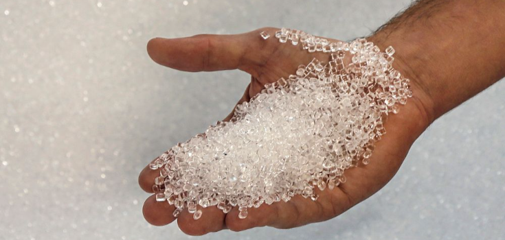
If you need clear, strong plastic parts that look good and last long, acrylic injection molding is a reliable way to make them. It produces parts that are lightweight, glossy, and resistant to sunlight and impact.
In this guide, you’ll learn what acrylic injection molding is, how the injection molding machine works, how it turns PMMA into finished parts, and why it’s trusted for making high-quality, precise plastic parts.
What is Acrylic Injection Molding?
Acrylic injection molding is a way to make plastic parts using acrylic, also known as PMMA or Polymethyl Methacrylate. You start by heating acrylic resin until it melts into a thick liquid. Then, an acrylic injection molding machine pushes the melted material into a mold under high pressure. After it cools and hardens, the part takes the exact shape of the mold.
This process helps you create strong, detailed parts that look clean and clear. It works well when you need many parts that are all the same size and shape.
Why Choose Acrylic?
There are many reasons why you might choose acrylic injection molding. Below are some of the advantages of acrylic injection molding:
- It will not turn yellow or break down while it’s in the sun or outside
- It will not break as easily because it’s stronger than glass when it comes to impact.
- Acrylic is easier to carry and move around because it’s lighter than glass.
- It usually costs less than glass and other clear materials, which helps you save money.
- You can cut, shape, and mold acrylic easily, which gives you greater freedom while designing your parts.
- You can easily add color, texture, or coatings to match your design needs.
- It uses lower processing temperatures, which saves energy and cuts down costs.
- It keeps its shape and size well, even when making large numbers of parts.
- It is resistant to many chemicals, making it suitable for industrial uses.
- It’s very clear, with light transmittance ranging from 91% to 93%, perfect for see-through parts.
- It’s 100% recyclable, making it more eco-friendly than glass.
Acrylic Material Properties
Here are the important properties of acrylic:
| Type | Value |
| Density | 1.13 to 1.19 grams per cm³ |
| Shrinkage Rate | 0.4% to 0.61% |
| Rockwell Hardness | 71 to 102 R |
| Tensile Strength | 6,390 to 10,700 PSI |
| Elongation at Break | 3% to 12% |
| Flexural Modulus | 247,000 to 509,000 PSI |
| Flexural Strength | 6,770 to 18,900 PSI |
| Impact Strength | 1.0 to 1.2 kJ/m² |
| Heat Deflection Temp | 85°C to 95°C before it bends |
| Thermal Conductivity | About 0.19 W/m K |
| Water Absorption | Around 0.3% to 0.5% |
| Drying Temperature | 75°C to 91°C |
| Drying Time | 3.4 to 5.1 hours |
| Melt Temperature | 225°C to 272°C |
| Mold Temperature | 59.4°C to 81.1°C |
The Process of Acrylic Injection Molding: Step-by-Step
Here’s how acrylic injection molding works, step by step:
Step 1: Prepare the Material
You start by drying the acrylic pellets for injection molding. This removes any moisture, which helps prevent bubbles or defects in the final part.
Step 2: Melt and Inject
You feed the dry pellets into the acrylic injection molding machine. The machine heats the pellets until they melt, then injects the molten acrylic into a mold under high pressure.
Step 3: Cool the Mold
Once the mold is filled, the acrylic cools down quickly and hardens into shape.
Step 4: Remove and Finish the Part
After cooling, the mold opens, and you remove the part. You may need to trim, polish, or paint it to get the final look you want.
Design Guidelines for Acrylic Injection Molding
When you’re working with acrylic injection molding, there are a few important design rules to follow. These help you avoid problems and make sure your parts come out clean and accurate.
Wall Thickness
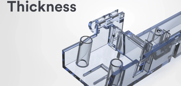
Keep the wall thickness between 0.025" and 0.150" (0.635 to 3.81 mm). Try to keep the thickness the same throughout the part. If the walls are uneven, the part may warp or crack.
Corners and Radii
Don’t use sharp corners. Instead, round them off. A good rule is to use a radius that is at least 25% of the wall thickness. For stronger parts, aim for 60%. This helps the acrylic flow better and reduces stress in the part.
Draft Angles
Add a draft angle of 0.5° to 1° on vertical walls. This makes it easier to remove the part from the mold. If you’re making clear parts, you may need a larger angle for a smooth finish.
Tolerances
For regular parts under 160 mm, you can expect tolerances between 0.1 mm and 0.325 mm.
For more precise parts under 100 mm, tolerances can be between 0.045 mm and 0.145 mm.
Processing Tips for Better Results

Here are some tips you can use when injection molding acrylic:
- Acrylic absorbs moisture, which can cause cloudiness or defects. Dry your acrylic pellets for injection molding for 3.4 to 5.1 hours before using them.
- Set the right acrylic injection molding temperature, not too high or too low. Too much heat can break down the material, causing burn marks. Too little heat won’t let it flow properly into the mold.
- Acrylic needs more pressure because it’s thicker when melted. Use just enough to fill the mold.
- Too much pressure can cause the part to stick; too little may lead to incomplete parts.
- Use a moderate injection speed. Going too fast can cause burn marks or a rough surface. Too slow, and the mold might not fill completely.
- Acrylic shrinks by 0.4% to 0.61% when it cools. Plan for this in your mold design. Shrinkage can change based on pressure, acrylic injection molding temperature, and how long you can hold the pressure.
Applications of Acrylic Injection Molding

You’ll find acrylic injection molded parts in many everyday and industrial products, like the following:
- Optical lenses
- Display panels
- Light covers
- Automotive tail lights
- Protective covers
- Medical device casings
- Signage and retail displays
- Aquariums
- Phone cases
- Cosmetic containers
- Lighting fixtures
- Glass replacement panels
DEK’s High-Quality Acrylic Injection Molding Services
At DEK, we provide clear, strong, and precise acrylic parts using advanced acrylic injection molding. We use the best acrylic pellets for injection molding and skilled processes to ensure your parts look great and work well.
Contact us today if you want reliable, high-quality acrylic injection molded parts made efficiently to meet your project needs.
Conclusion
To wrap it up, acrylic injection molding is a great way for you to make clear, strong, and detailed plastic parts that last long. This process saves energy, resists chemicals, and is recyclable. You heat acrylic and shape it in a mold to get parts that are light and durable. By following the right steps and design rules, you’ll get parts that look great and perform well.
FAQs
What temperature is acrylic molding?
Acrylic molding typically happens between 160°C and 210°C, depending on the specific grade of PMMA.
Can acrylic injection molded parts be customized with colors or textures?
Yes. You can customize acrylic injection molded parts with different colors, textures, and surface finishes to match your design.
How does acrylic injection molding differ from other plastic molding processes?
Acrylic injection molding is different from other plastic molding processes because it focuses on producing clear, strong parts with high precision, using specific temperatures and drying steps to prevent defects.
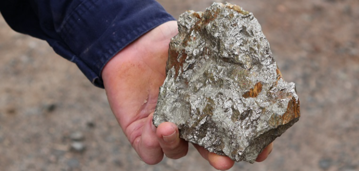
Nickel is a strong, silver-colored metal used in many things like stainless steel, batteries, and jet engines. One important property of nickel is its density.
Understanding the density of nickel helps you know how heavy it is and how it performs in different applications. In this guide, you’ll learn what nickel is, how its density is measured, and how it compares to other metals.
What is Nickel?
Nickel is a metal with the symbol Ni and the atomic number 28. At room temperature (around 20°C or 68°F)
What is the Density of Nickel?
The density of nickel is about 8.907 grams per cubic centimeter (g/cm³). This means nickel is heavier than many other metals of the same size, which affects how it’s used in different products.
Density in Different Units:
In kilograms per cubic meter (kg/m³): About 8,907 kg/m³
In pounds per cubic inch (lb/in³): About 0.323 lb/in³
Measurement and Calculation of Nickel Density
To measure the density of nickel metal, you can use a few simple methods. One way is by using Archimedes’ principle. In this method, you drop the metal into water and see how much water it pushes out. That tells you the volume. Another way is to measure the metal’s weight (mass) and size (volume) and then use a formula to find the density.
Factors Affecting Nickel’s Density
These are the few things that can change the density of nickel metal:
Temperature

Nickel’s density changes with temperature. When it gets hotter, the metal expands a little, which makes its density drop slightly. When it cools down, the metal shrinks, so the density go up a little.
Alloy Composition
Nickel is often mixed with other metals, like in stainless steel, which changes its density. For example, stainless steel has nickel, chromium, and other metals, so its density is different from pure nickel.
Purity of the Metal
Pure nickel has a steady density of about 8.907 g/cm³. But in real-world uses, nickel is usually mixed with other metals, which can change its density. High-purity nickel, used for precision work, stays close to that 8.907 g/cm³ density.
Challenges in Machining Nickel
You also need to know the challenges when machining nickel to help you get better results:
Work Hardening
Nickel hardens quickly while being worked on. This means it gets harder and stronger as you machine it, which can wear out your tools faster and make it harder to keep things precise.
High Cutting Forces
Nickel is tough and strong, so it needs more force to cut than other materials. This puts extra stress on your tools and machines, so you’ll need strong and high-quality equipment to handle it.
Thermal Conductivity
Nickel doesn’t transfer heat well, so it can get really hot during machining. You’ll need good cooling methods to avoid overheating, damaging your tools, or causing the workpiece to warp.
Applications of Nickel
Nickel is a flexible metal with many uses, and here are some of its main uses that you might encounter:
Stainless Steel Production
Nickel is an important part of stainless steel, making up about 8-12%. When added to steel, it helps the material resist rust and corrosion. This makes it great for things like kitchen tools, cutlery, industrial equipment, and construction materials.
Battery Manufacturing
Nickel is used in many types of batteries, like nickel-cadmium (NiCd), nickel-metal hydride (NiMH), and lithium-ion. You’ll find it in rechargeable batteries for electronics, electric cars, and power tools because it holds a lot of energy and works well in different temperatures.
Electronics and Electrical Components
Nickel’s magnetic and corrosion-resistant qualities make it useful in electronics. It’s used in connectors, switches, and other parts. You may also see nickel plating applied to improve the conductivity and durability of electrical contacts.
Aerospace and Defense

Nickel alloys are used in the aerospace and defense industries because they’re strong heat-resistant, and can handle tough conditions. You’ll find nickel-based superalloys in things like turbine engines and rocket nozzles, which need to perform well under high temperatures and pressures.
Marine Applications
Nickel alloys are used in marine environments to resist seawater corrosion. You’ll find these alloys in shipbuilding, offshore platforms, and other marine equipment, helping them last longer and work reliably in tough conditions.
Nickel Density vs Other Metals
When you compare nickel to other metals, its density gives you an idea of how heavy and strong it is. Nickel is denser than aluminum (2.70 g/cm³) and titanium (4.506 g/cm³), which makes it heavier but also stronger for some uses. This is important when you choose materials for things like structural parts, where both weight and strength matter.
Nickel is less dense than metals like lead (11.35 g/cm³) and tungsten (19.3 g/cm³), which are much heavier and used in situations where you need more mass or strong shielding. Still, nickel’s higher density compared to lighter metals gives it the strength and durability needed in tough environments.
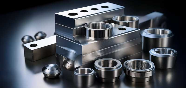
DEK for Precise Nickel Parts Machining Services
At DEK, we make high-quality nickel parts that are strong, durable, and resistant to corrosion. Whether you need parts for aerospace, electronics, or other industries, we ensure each one meets your needs with precision.
Let us help you machine the right nickel parts for your projects, so they perform well and last longer. Reach out to us today to discuss how we can support your manufacturing needs.
Conclusion
The density of nickel metal is 8.907 g/cm³, and it gives nickel its strength, durability, and resistance to corrosion. This is the reason why it is an important material for high-performance and industrial uses.
In short, nickel’s density affects its physical properties and determines how useful it is in areas like engineering, manufacturing, electronics, and more.
FAQs
What is the density of nickel oxide?
Nickel(II) oxide (NiO) has a density of approximately 6.72 grams per cubic centimeter (g/cm³) at room temperature.
What is the density of nickel aluminum bronze?
Nickel aluminum bronze alloys, such as C95800, have a density of about 7.64 g/cm³ at 20°C.
How does the true density of nickel differ from the theoretical density of nickel?
The true density of nickel, measured experimentally, is approximately 8.907 g/cm³. The theoretical density, calculated based on its crystal structure, is slightly higher at 8.917 g/cm³
What is the density of nickel at 20 degrees Celsius?
At 20°C, the density of pure nickel is approximately 8.907 g/cm³
If you work with machined, stamped, or cast parts, you know that burrs can be a big problem. These small but unwanted bits of material can affect the quality, safety, and performance of your parts.
In this deburring guide, we’ll discuss the different methods and types of deburring.
What is Deburring?
A burr is a rough edge or extra metal on the surface of a metal piece. It can appear as a jagged edge on metal cut with a cold saw, hot saw, or flame cutter, or as excess metal along a welded seam. When metal is cut with a cold saw, burrs usually form at the ends, and their size depends on the gap between the cutting blades.
Since burrs can’t be completely avoided, some amount is usually acceptable. However, for welded tubes, the burrs inside and outside must be removed because they can affect how the part works. In machining, different deburring tools help you shape parts accurately by smoothing out the rough edges.
Why Do They Form and How?

Burrs can form for many reasons when you cut sheet metal. Here are the most common causes:
- Harder materials don’t cut easily. They can resist the tool and break into rough edges.
- If you cut too fast, the heat and pressure can make the material deform, leading to burrs.
- A dull or worn-out tool won’t cut cleanly, which can cause uneven edges and burrs.
- If you use the wrong lubricant, friction and heat increase, making burrs more likely.
- If your tool isn’t the right shape or size for the job, it might push the material instead of cutting it smoothly.
- If you move the tool too fast, the material can’t handle the pressure and forms burrs. If you go too slow, material can build up on the tool and also cause burrs.
- Too much heat can soften the metal, making it easier for burrs to form.
- If the surface is rough, the tool might not cut evenly, increasing the chance of burrs.
- An irregular cutting path can create uneven cuts, leading to burrs.
- The way the tool leaves the metal affects how clean the edge is. A bad angle can cause burrs.
- Smaller edges concentrate stress, making the metal more likely to burr.
- If the material is too flexible, it may bend instead of cutting cleanly, creating burrs.
- Too much vibration can make the tool move off course, causing rough edges.
- If you use too much force, the material can shift and form burrs. Too little force can also cause incomplete cuts, leading to burrs.
- The way the metal is made (its grain and composition) affects how it reacts when cut, which can lead to burrs.
Why Deburring Matters?

Burrs might look like small flaws, but they can cause big problems if you don’t remove them:
- Sharp burrs can cut or injure you when handling parts.
- They can make the product look bad, not fit right, or not work properly.
- Burrs can get in the way when putting parts together.
- Burrs can trap moisture and dirt, leading to rust and damage.
- Burrs make equipment wear out faster.
- Burrs prevent precise machining.
Different Types of Burrs
Burrs can be grouped into two main types based on their shape and how they form.
Types of Burrs by Shape

Flying Edge Burrs
Flying edge burrs, also called spills or flash, usually appear where two mold parts meet or where a machine clamps down. They often happen when the mold or machine doesn’t press tightly enough.
Sharp Burrs
Sharp burrs look like broken glass with sharp edges. They can be firmly attached to the surface, and the lower side of the cut may feel rough.
Splashes
Splashes occur when molten metal accidentally sprays outside the main work area. After cooling, it hardens into uneven spots on the surface or edges.
Types of Burrs by How They Form

Poisson Burrs
Poisson burrs form when pressure stretches the edges of the material. This can also happen when a cutting tool presses against the metal, creating a burr at the entry point.
Tumbling Burrs
Tumbling burrs happen when leftover material folds over as a cutting tool moves. Deeper cuts can make burrs worse. Using flexible materials can help prevent them.
Tear Burrs
Tear burrs appear when the material is pulled apart instead of being cut cleanly.
Cut Burrs
Cut burrs are leftover material from cutting, sawing, or machining. They can look like raised bumps or rough edges.
Hot Burrs
Hot burrs, also called slag or splatter, form when molten metal hardens after welding, plasma cutting, or laser cutting. They happen because of uneven cooling and leftover heat stress.
4 Different Types of Deburring

Deburring methods can be grouped into four main categories.
Coarse Level (Hard Contact)
In this method, you use tools like files, sandpaper, and abrasive heads to remove burrs. It includes processes like cutting, milling, filing, and troweling. Most companies use this method because it is simple and easy to do.
However, it only works well for parts with basic shapes and external burrs. It does not remove burrs from complex parts with small holes. Since this method is mostly done by hand, it takes more time and can be expensive due to labor costs.
General Grade (Soft Contact)
This method includes belt grinding, polishing, sandblasting, and vibration. Many companies use it as the first step to remove large surface burrs. It can clean a large area at once, so it is useful for small parts made in large quantities. However, it does not always remove all burrs, so you may need to do additional manual deburring or use another method to finish the process.
Fine Grade (Flexible Contact)
This method includes processes like flushing, electrochemical machining, electropolishing, and rolling. Some companies use high-precision dies and punching machines to remove burrs more accurately. This method is much faster and more effective than manual deburring.
However, you may need to invest in special tools, which can be costly. It works best for parts with simple shapes and is a good choice if you need a more precise and efficient deburring process.
Ultra-Precision Level (Accurate Contact)
This method includes advanced techniques like friction flow deburring, magnetic milling deburring, and electrolytic deburring (ECD). In ECD, a chemical process dissolves the burrs quickly. The workpiece is connected to a power source, and a liquid solution flows over it. When electricity is applied, the burrs dissolve and are removed.
However, because the solution is corrosive, you must clean and protect the part from rust immediately after deburring. This method is very fast, often taking only seconds or minutes, and is excellent for removing burrs from hard-to-reach areas. However, it is more expensive because it requires special equipment and materials
Step-by-Step Deburring Process
Follow these steps to prepare:
Choose the Right Tool

Pick a tool based on the type and size of the burrs. Use mechanical tools for big burrs and special methods like electrochemical deburring for precise work.
Check the Material
Look at the material and how much burring there is. Different materials need different deburring techniques.
Set Up the Tool
Make sure your tool is set to the right speed, pressure, and angle. This is important for machines and automatic deburring systems.
Check for Safety
Inspect all equipment to avoid accidents. Make sure everything is fitted correctly, safety shields are in place, and guards are secure.
Do a Test Run
Try the tool on a sample piece first. If needed, adjust the settings to get the finish you want.
Most Practical Methods of Deburring
There are different ways to remove burrs, including mechanical, manual, electrochemical, and thermal deburring.
Mechanical Deburring

This method uses special tools like brushes, milling cutters, and polishing tools to remove burrs. It works well for both inside and outside edges, making them smooth and rounded. Mechanical deburring is great for parts with complex shapes.
Manual Deburring
With this method, you remove burrs by hand using different tools. It is flexible and can be used on many types of parts, but it takes more time than other methods.
Electrochemical Deburring
This method remove burrs from hard metals quickly and safely using an electrical process.
Thermal Deburring
This method uses a mix of fuel, oxygen, and heat to burn away burrs. It is an effective way to clean up parts.
Automated Deburring
Automated deburring smooths rough edges on machine parts, so they are safer and improve production. It works faster and better than manual deburring, reaching all edges with ease. Using automated systems helps you remove burrs quickly and manage the process more easily.
Manual Deburring vs Automated Deburring

If you do deburring manually, you use hand tools like files or brushes. This is good for small jobs or tricky shapes, but it takes time and can be uneven. Automated deburring uses machines or robots, so the process is faster and more consistent, especially for big projects. It costs more at first but saves money on labor over time.
Choose manual if you need flexibility, and go with automation if you want speed and accuracy.
Deburring Tools and Equipment
You can use different tools depending on the material and the job. Here are some common deburring tools and equipment:
Manual Tools
Deburring Knives: You can use a deburring knife to remove burrs by hand. These knives give you good control. They are great for small or delicate parts.
Scrapers: Scrapers help you remove burrs from flat surfaces and edges. They come in different shapes and sizes to fit different materials.
Mechanical Equipment
Deburring Machines: Deburring machines do the job automatically, faster, and more consistently. These machines are useful for large projects and different types of materials.
Tumblers and Vibratory Finishers: They shake or rotate parts with abrasive materials to remove burrs. These machines are great when you need to finish many small parts at once.
Advanced Deburring Systems
Laser Deburring: Laser deburring removes burrs with a high-powered laser. This method is very precise and works well on materials that could be damaged by physical tools.
Robotic Deburring: Robotic deburring uses programmed robots to remove burrs. This system is best for detailed or repetitive tasks because it is fast and accurate.
Material-Specific Deburring Tips

Different materials require specific deburring techniques to achieve the best results. Here’s how you can approach deburring for various materials:
Metal
For aluminum, vibration, sandblasting, or rollers work well, but some burrs may still need manual removal. Stainless steel is tougher, so using special tools makes the process easier.
Plastic & Composite
Plastics can be deburred with tumbling, sanding, or abrasive blasting to smooth the edges. Composites require careful handling to avoid damage, so water jet cutting or hand tools are the best options.
Exotic Alloy
Titanium is difficult to deburr and can overheat, so specialized tools are needed. Inconel is a strong material that requires high-energy methods like centrifugal disc finishing for the best results.
Which Method Is Best for Your Project?

Choosing the right method depends on your industry and manufacturing needs. To know which method to use, follow these:
Know Your Material and Part Shape
Different materials need different deburring methods. Metals, plastics, and rubber react differently. Complex parts may need precise methods like Laser or Electrochemical deburring, while simple parts work with mechanical or manual methods.
Identify the Type of Burrs
The location and type of burrs matter. Thermal deburring works well for internal burrs, while Cryogenic deburring is best for materials that become brittle in the cold.
Evaluate Production Volume
For large production runs, automated methods like mechanical deburring save time and money. For small batches or prototypes, manual deburring is a more affordable choice.
Factor in Cost and Resources
Some methods, like Laser or Electrochemical deburring, require expensive machines and training. Manual methods need skilled workers but cost less upfront.
Assess the Required Level of Precision
High-precision industries, like aerospace and medical, need more advanced deburring methods. Less critical parts can use simpler, cheaper options.
Safety and Environmental Considerations

Some methods, like thermal deburring, require strict safety rules. Also, consider how the process affects the environment, especially if it produces waste or emissions.
Turnaround Time
Some deburring methods take longer than others. If you have tight deadlines, choose a faster method that still meets quality standards.
Conclusion
Deburring is an important step in manufacturing that helps improve the quality, safety, and performance of your parts. By choosing the right deburring method, you can ensure smooth edges, prevent defects, and extend the lifespan of your equipment.
DEK offers expert deburring services and high-precision solutions to help you achieve smooth, flawless parts with efficiency. Contact us today to optimize your manufacturing process!
If you work with metal or plastic parts, you’ve probably heard about Vertical Machining Centers (VMCs). These machines are widely used in manufacturing to cut, shape, and drill materials with precision. Let’s discuss more about vertical machining centers in this informative guide.
What is a Vertical Machining Center?
A Vertical Machining Center (VMC) is a powerful tool used in CNC machine shops. It is designed to help you create precise holes and shapes on flat surfaces. The machine operates in a vertical direction, using a spindle that moves up and down at a steep angle.
With computerized controls, a vertical machining center can automate tasks like selecting and rotating tools, repeating movements, and shaping materials with accuracy. These advanced CNC machines have greatly improved milling productivity. Different models vary in how many axes they have, what functions they can perform, and the extra features they offer.
You can think of a vertical machining center as a reliable and efficient workhorse in manufacturing. It delivers parts with high accuracy in less time. Its strong design allows it to provide excellent torque, power, and speed. Because of its high level of automation, it can work with different materials while also helping to lower production costs.
Basic Working Principles of Vertical Machining Centers

A vertical machining center works by following a design model of the parts you want to make. The machine tools and settings needed for the parts are turned into code that the machine’s numerical control system can understand.
The machine follows a processing program that runs the CNC instructions automatically. These instructions are usually stored on disks or punched tapes, which are then sent to the machine’s input device. You can read this information and transfer it to the numerical control system. You can also send the program directly using a computer connected to the machining center.
A vertical machining center typically moves in three directions (X, Y, and Z). It also has a rotating table attached to the work surface, which makes it easier to create circular parts.
Main Parts of A Vertical Machining Center

A vertical machining center has several important parts that work together to make parts according to manufacturing standards. These include:
Rotating Spindle
The spindle is a spinning shaft that holds the cutting tool or workpiece. It is usually placed vertically (up and down) and helps position, support, and rotate the workpiece during machining.
Rotating Tables
Adding extra rotating axes turns a basic 3-axis machine into a 4-axis or 5-axis machine. This allows you to make complex parts, like turbine blades, more easily.
Work Table
This is a flat surface where you place the workpiece. You can secure it directly or use clamps and fixtures. The table moves in three directions:
- X-axis (left and right)
- Y-axis (front and back)
- Z-axis (up and down)
This movement allows you to add different features to your workpiece.
Tool Changer
This system automatically switches tools for different tasks. It makes the machining process faster and more efficient.
Coolant System
Most machines use a coolant system that recirculates liquid (such as water mixed with oil) to keep the cutting tools and parts cool and lubricated.
Quick Loading Loaders
Automated loaders, such as shuttle tables, help place parts quickly, reducing downtime, and increasing efficiency.
Enclosures/Full Covers
These covers keep metal chips and coolant from splashing around. They also help protect the machinist and keep the work area clean.
Screw/Chip Conveyor
This system automatically removes metal chips from the work area, so you don’t have to shovel them out by hand. It helps keep the machine running smoothly.
Common Uses of Vertical Machining Centers

If you’re new to this technology, looking at a vertical machining center diagram can help you understand how it works. It has a vertical spindle, which moves up and down, and a table that holds the material you are machining. You may also ask, “What can you make with a vertical machining center?” Well, here are some of them:
Shaping Complex Parts
Some parts, like baskets or bases, have irregular shapes that are hard to machine. A vertical machining center with pallet changer makes it easier to create these complex parts by allowing you to switch workpieces automatically.
Making Box-Shaped Parts
Box-type parts, such as engine blocks and gear pump shells, have multiple cavities and hole systems. These are common in cars and airplanes. A double column vertical machining center is ideal for machining large, heavy parts with high precision. This type of machine provides extra stability and strength.
Cutting Curved or Detailed Designs
Some parts, like propellers, cams, and impellers, have detailed curves and contours. A vertical spindle machining center helps create these complex shapes with high accuracy. It is especially useful in industries like aviation and transportation, where precision is important.
Producing Prototype Parts
If you need to create new parts or test different sizes, a vertical machining center gives you flexibility. You can quickly change the program, resize parts, or adjust production settings. So, it is ideal for small batches and new product testing.
Machining Flat and Cylindrical Pieces
You can use a vertical machining center to make board, sleeve, and plate parts. These parts often have keyways or radial holes. Examples include shaft sleeves and plates with multiple holes, like motor covers. A vertical machining center helps you machine these parts quickly and accurately.
Benefits of VMC
There are many advantages of using a vertical machining center, and some of them are the following:
Boosts Production Speed

VMCs help you get work done without reducing quality or wasting resources. Automation makes them even more efficient by handling setup tasks separately from the actual machining.
Easy to Use and Saves Time
VMC machines are designed so you can see your work clearly. This helps you spot and fix problems quickly while milling. The simple CNC controls make programming easier, and the machine design allows you to set up workpieces faster. This means you spend less time on setup and programming.
Takes Up Less Space
A VMC takes up only about one-third of the space of a horizontal machining center. Because it saves a lot of space, a VMC is a great choice for small businesses.
More Affordable Than Horizontal Machines
A vertical machining center costs less than a horizontal machining center. The initial investment is lower, and you can also save money on production costs.
Vertical Machining Center Features
Below, we discuss the features that a vertical machining center possesses.
Strong Metal-Cutting Ability

Your vertical machining center should be able to cut a wide range of materials. Good cutting ability is key to boosting productivity. That’s why the spindle is one of the most important features to consider when choosing a machine.
Fixturing and 4th-Axis Potential
A good machine should make it easy to set up fixtures and use a 4th axis when needed. If the software is too complex, it slows you down. A simple and efficient system saves time and boosts machine uptime.
Advanced Control Software
Your machine’s software can either help or limit how you store data, set up coordinates, probe, and network. If the interface is hard to use, you’ll waste time solving problems instead of working. A simple, user-friendly system keeps things running smoothly.
Tool Support and Capacity
You need your VMC to handle different parts, switch between jobs quickly, and maintain tool quality. If the machine isn’t designed for this, it can lead to frequent downtime, higher costs, delays, and lost profits. That’s why having a machine with strong tooling support and good cooling capacity is essential.
Automation Options

Automation helps different hardware and software work together as one system. This reduces the need for manual labor and increases productivity.
Comfortable Design for Operators
Your machine should be comfortable and safe to use. Automation can help by giving you more time and space to set up workpieces, improving your overall work environment.
Difference Between Horizontal and Vertical Machining Center
CNC machining carters are advanced machines that help automate cutting and shaping materials. The two main types are vertical machining centers (VMCs) and Horizontal Machining Centers (HMCs). Here’s how they are different:
Spindle Direction
The biggest difference is how the spindle (the part that holds the cutting tool) is positioned. HMCs have a spindle that lies sideways. This allows them to make deeper cuts. VMCs have an upright spindle, so they are better for precise cuts.
Cutting Precision and Accuracy

HMCs remove more material because they are more stable. They work well for heavy cutting jobs. VMCs are better for detailed work like making grooves and smooth surfaces but remove less material.
Tool Design Differences
HMC tools are shorter and thicker, which makes them more stable when cutting deeper into materials. VMC tools are thinner and longer, allowing for more precise cutting, but they can vibrate more which affects accuracy.
How Many Sides Can Be Machined
VMCs (especially 5-axis models) can easily work on multiple sides of a workpiece. This improves efficiency and reduces mistakes. HMCs have more limitations when it comes to machining multiple sides.
Price Comparison
HMCs are more expensive to buy, run, and require experienced operators. This increases production costs. VMCs are cheaper and easier to use and maintain, that’s why they are ideal for small-scale production.
Choosing the Right Machining Center

Before buying a machining center, consider these factors:
- The type of material you work with will determine which tools and cutters you need.
- The VMC should produce parts quickly while maintaining high quality and using as few resources as possible.
- Make sure the VMC can meet your accuracy needs. Check if the machine and tools perform the way you expect.
- Regularly checking and replacing parts keeps the machine working well and producing high-quality products. Ignoring maintenance can lead to more defective parts, which increases costs for your business.
- Choose a system that is easy to use and can be programmed easily. Make sure you can get support and spare parts when needed for long-term use.
Conclusion
A vertical machining center is an essential tool for precision machining. It can help you shape complex parts, produce prototypes, or increase production speed.
Looking for high-quality machining solutions? At DEK, we offer top-tier vertical machining centers that produce precision parts and provide full-scale production support. Contact us today for a free, no-obligation quote!
If you work with electronics, you know how important it is to have precise and reliable parts. CNC machining in the electronics industry ensures that these components meet strict quality standards. It uses computer-controlled machines to cut, shape, and drill materials with extreme accuracy.
In this guide, explore the common CNC electronic components, the techniques and common materials used to make them, surface finishes that can be done, and so much more.
Why CNC Machining is Widely Used in the Electronics Industry

The electronics industry is huge, with different sections. The biggest is B2B e-commerce, which includes payment and communication tech for business transactions. In 2017, it made $29 trillion.
Other key areas include tech companies, consumer electronics, semiconductors, and power electronics. Electronics products use tiny parts like transistors, capacitors, and chips. These are found in computers, TVs, radios, and smartphones.
CNC machining is fast and precise, that’s why it is great for electronics manufacturing. It works with metals and plastics, avoids 3D printing issues, and allows easy design changes. Many electronics need extremely precise parts, and CNC machining is one of the best ways to make them.
Benefits of CNC Machining in Electronics

Now, let’s look at why CNC machining is a good choice for making electronic components. Here are some of the advantages:
Very Precise
CNC machines are extremely accurate. They can create small, complex parts for electronics or larger components like a laptop’s aluminum shell. Because CNC machines work with tight tolerances, parts usually don’t need much finishing before they’re ready to use.
Fast Production Time
Making electronic parts with CNC machining is quick because it doesn’t require complex tools. Even though it’s fast, CNC machining produces higher-quality parts compared to other quick methods like 3D printing.
Works with Many Materials
CNC machining supports many different materials. That’s why it’s often used for making prototypes of electronic parts.
Reliable for Production
CNC machining is dependable, so manufacturers use it for both small and large production runs. It’s also great for making prototype parts before full production.
Common CNC Electronic Components
CNC machining is used to make many electronic components, including the ones below:
Electronics Casings and Enclosures

You can use CNC machining to make strong and stylish casings for electronic devices like smartphones, cameras, and laptops. These enclosures protect the internal parts and give the device its shape.
While other methods like die casting or molding are common, CNC machining is better for complex designs and smooth finishes. You can use solid materials like aluminum for strength, apply different surface finishes like anodization, and even add engraved details or threaded features for a professional look.
Heat Sinks
Electronic devices like computers get hot, and heat sinks help cool them by moving heat into the air or a liquid coolant. CNC machining is a great way to make heat sinks, even in small sizes, because it allows for unique fin patterns that improve cooling.
Most heat sinks are made from aluminum or copper, but you can also use stainless steel or Inconel. CNC machining is perfect for short-run production or prototyping since it offers custom fin designs, works with different materials, is fast, and provides high precision for small parts.
Semiconductors

Semiconductors power modern electronics by replacing bulky vacuum tubes with tiny, efficient components. As the demand for smaller and more precise semiconductor parts grows, CNC machining plays a key role.
Most semiconductors are made from silicon or germanium. CNC machining ensures they are made with extreme accuracy. However, only a few companies have the right expertise and machines for this process.
Consumer Electronics
From smartphone frames to laptop bases, CNC machining creates smooth finishes and precise fittings. These parts need to look good and be strong enough for daily use—something CNC machining does best.
For example, in smartphones, CNC machines create tiny mounts and supports that securely hold delicate electronic parts. This precision helps devices last longer and work properly.
Wearable devices also rely on CNC machining to make small, complex parts that fit perfectly in tight spaces. This accuracy makes CNC machining essential in consumer electronics.
Connectors and Sockets

Many electronic devices connect to others using plugs, sockets, and cables. Examples include USB keyboards, headphones, and musical instruments.
CNC machining is used to make these small metal connectors with extreme precision for secure connections. If a connector’s pins or a socket’s opening are even slightly off, the connection may fail.
Common machined parts include sockets, pins, and contacts, often made from copper alloys.
Electronic Switches
Every electronic device has switches to control power, from mobile phones to large computer servers. CNC machining helps create switches with the right shape and size to ensure they fit perfectly.
Metal switches often require tight tolerances to ensure smooth movement and durability, while plastic switch casings need to fit perfectly around internal components.
Printed Circuit Boards (PCBs)

PCBs are in almost all electronic devices, connecting different parts with copper tracks on a non-conductive base. Most PCBs are made using chemicals in a process called etching, but this is not always safe for small workspaces.
CNC machining is a safer way to make PCBs since it doesn’t use chemicals and still provides high precision. With CNC machining, you can create PCBs in-house, and it is perfect for prototyping. It allows for quick production, easy design using CAD/CAM software, and lets one machine handle multiple steps.
Common Materials Used in CNC Machining for Electronics
CNC machining can work with many types of materials, including metals and non-metals. Below are some common materials used to make electronic devices.
Metals

Aluminum: This metal is light, resists rust, and conducts electricity well. You’ll often see it in electronic parts like heat sinks and enclosures, where controlling heat is important.
Stainless Steel: Strong and rust-resistant, stainless steel is used for screws, enclosures, and mechanical parts in electronic devices.
Brass: This metal resists rust and conducts electricity well, it’s used in connectors, switches, terminals, and decorative parts.
Copper: Copper is great at conducting heat and electricity. It’s used for electrical contacts, circuit board parts, and heat exchangers.
Non-metals
Plastics: Lightweight and durable plastics like PEEK, ABS, polycarbonate, and acrylic are used for insulation, display covers, and housings. They can also resist scratches and impacts.
Composites: these are made by mixing two or more materials. They are strong, resist flames, and provide electrical insulation. They are ideal for structural parts and insulators.
CNC Techniques for Machining Electronics
Here are some common CNC machining methods used in electronics production:
CNC Milling

CNC milling uses a spinning cutting tool to remove material from a workpiece, shaping it into the desired form. This method is used to make circuit boards, electronic connectors, and heat sinks.
CNC Turning
CNC turning creates round or cylindrical parts by spinning the material while a cutter removes unwanted sections. It is often used to produce connectors, pins, fasteners, and spacers for electronics.
CNC Drilling
CNC drilling is used to make precise holes in electronic components. It is essential for creating through-holes in circuit boards and for placing LEDs, connectors, and buttons.
CNC Engraving
CNC engraving uses a laser or cutting tool to mark parts with logos, text, patterns, or serial numbers. This technique is commonly used on circuit boards, enclosures, and display panels to ensure accuracy and avoid mistakes.
Surface Finishes for CNC Electronics Components

Surface finishes make CNC-machined electronic parts look better, last longer, and work more efficiently. Here are some common types:
Bead Blasting: This process removes small surface flaws and gives parts a smooth, matte look.
Electroless Nickel Plating: A popular choice because it improves conductivity and protects against wear and corrosion.
Anodizing: Creates a non-conductive, corrosion-resistant layer on the surface. It comes in different colors and helps with durability.
Powder Coating: Adds a tough, colorful protective layer that resists corrosion.
Passivation: Cleans the surface and removes contaminants. This finish makes the part more resistant to rust while keeping a natural finish.
Polishing: Gives parts a shiny, reflective look and smooths the surface to reduce friction.
Challenges of CNC Machining in Electronics

Although CNC machining does offer many advantages, you may encounter some challenges too– like the following:
- Ceramics and other brittle materials can break or chip easily when machining.
- Setting up CNC machines and tools is expensive, especially for small projects.
- You need trained programmers and operators to run the machines correctly, which adds to the cost.
- Machining creates heat, which can damage delicate electronic parts if not managed properly.
Get High-Quality CNC Machined Electronic Components With DEK
At DEK, we provide on-demand CNC machining, making prototypes and production parts quickly with different materials. We serve many industries, including electronics, military, aerospace, medical, and automotive.
Let’s work together to turn your electronic designs into high-quality, precise parts. Visit our website or reach out to us to see how we can help with your next project in the electronics industry.
Conclusion
CNC machining is a great way to make strong and precise electronic parts. It works fast, uses many materials, and gives you reliable results. There are some challenges, like high setup costs and heat issues, but the benefits make it worth it. With CNC machining, you can create high-quality parts quickly and easily.
FAQs
Is CNC machining or 3D printing better for electronic device manufacturing?
It depends on what you need. CNC machining is more precise and stronger, especially for metal parts. It also works with many different materials.
What factors affect the cost of electronics CNC machining?
Several things can make CNC machining more expensive, including how complex the design is, how precise the parts need to be, the material you choose, and how many parts you need to make.
CNC machining is a process that helps to manufacture a wide range of components with precision-oriented features. The lathe cutting tools are also used with CNC machining to cut components and achieve different geometrical features.
The guide below will help you understand each type of lathe tool and its function.
What are Lathe Cutting Tools?
A lathe cutting tool is a very important and versatile tool that is used with turning operations in CNC machining. The tool rotates the workpiece on its axis, and the cutting tools remain stationary, removing the material from the component. It helps to create symmetrical profiles about the rotation axis and may handle simple to complex components.
Components of a Lathe Cutting Tool

There are different components of a lathe cutting tool, and some of these are as follows:
Headstock: The headstock is a very important component, and it is present on the left end of the machine. It has gears, a spindle, and a motor that drives the spindle; the main function of the headstock is to rotate the workpiece by holding it.
Tailstock: It is at the back of the headstock and supports one of the ends of the workpiece. It holds the tools in the form of drills and carries out the drilling operation.
Bed: The lathe’s bed works like a support that holds the major components, like the tailstock and headstock of the machine.
Carriage: The carriage is present along the bed and holds the cutting tool, which helps the cutting tool move in different directions.
Lead Screw: It is a shaft with a long length having threads and is located parallel to the bed. It helps with precise threading processes and moves the carriage.
Feed Rod: The feed rod is present along the lead screw; it offers carriage movement for operations involving non-threading features.
Spindle: The spindle rotates the workplace, and the workpiece is mounted in it.
Types of Lathe Cutting Tools
There are different types of lathe cutting tools, and each of them is discussed below.
Type 1: Lathe Cutting Tools Based on Material
There are different materials used for manufacturing lathe cutting tools, and some of these are as follows:
High-speed Steel(HSS)

The high-speed steel has carbon, tungsten, vanadium, and chromium, which makes it suitable for use on components equipped with hardness. They work at high speed and cut the harder metals with precision and finishing.
Carbide
Carbide lathe cutting tools offer brittleness and hardness, and hence work with versatile materials. They are, however, expensive and are used in part manufacturing for limited purposes.
Diamond
Lathe cutting tools, which are made using diamonds, are exceptionally hard. They are suitable to be used for all types of materials and are highly expensive.
Cubic Boron Nitride

Cubic boron nitride is also a hard and durable material, which makes the lathe-cutting tools abrasion-resistant and suitable for intermittent cutting.
Ceramic Lathe Tool
Ceramic lathes are highly resistant to wear and are suitable for advanced industrial applications.
Type 2: Lathe Cutting Tools Based on Operations
Lathe-cutting tools are also based on different operations, and each of these is discussed below.
Turning Tools
Turning tools help to remove material through the length of the workpiece, reducing its diameter. Rough turning tools move a bulk amount of material from the workpiece in one go. Hence, they can create rough shapes. Whereas the finishing turning tools remove a small amount of material from the workpiece and create a finished surface.
Chamfering Tools

Chamfering tools are meant to produce a slant edge, and these are suitable for chamfering. They can be placed at the right lathe cutting tools angles so that the inclination is correctly achieved.
Thread Cutting Tools
Thread-cutting tools create patterns of spiral threads on the components, which are cylindrical. They have a nose angle, and it depends on the third angle intended.
Facing Tools
Facing tools use the side cutting edge and move the material in the form of a thin layer.
Forming Tools
Forming tools consist of a grooving and turning tool, which helps create complex shapes.
Grooving Tools

Grooving tools make grooves on the components that have cylindrical shapes.
Boring Tools
Boring tools consist of a boring bar that helps increase the size of the hole diameter.
Knurling Tools
Knurling tools consist of metal rolling wheels that have embossed patterns. They help create parts that have increased grips.
Type 3: Lathe Cutting Tools Based on Structure
Lathe-cutting tools have different structures, and the classification is featured below.
Single Body Tools
Single-body tools have a single piece of material that is designed to attain a specific geometry and size, and they are the most common ones to go for.
Welding Lathe Cutting Tools
Welding lathe cutting tools consist of a rod and head, which are made using different materials and are connected with the help of welding. The flank is from materials like carbide, and the body is from a different metal. These metal lathe cutting tools offer less cutting force as they are made with different materials.
Clamp Lathe Cutting Tools

Cutting tools that have the same composition of the material and consist of an insert on the handlebar are called clamp lathe cutting tools. These tools can be replaced and have properties like durability and strength.
Type 4: Lathe Cutting Tools Based on Feed Direction
Lathe cutting tools, which are based on the feed direction, are the following:
Right-Hand Lathe Cutting Tools

These tools help to remove material when they are transported from right to left. The design is the same as a human hand and has a thumb on the right, indicating the feed direction.
Left-Hand Lathe Cutting Tools
Left-hand lathe cutting tools help to remove material when they are transported from left to right. The direction of the feed is indicated by the left thumb, and the cutting edge lies on the right side of the tool.
Round Nose Lathe Cutting Tools
Round nose lathe cutting tools help create a smooth surface, which they do by moving in the left and right directions.
How to Select the Right Lathe Cutting Tool?

When selecting the right lathe-cutting tool, some of the considerations to have in place are as follows:
- The lathe cutting tools with coatings are durable and can work well. The addition of a layer of coating not only enhances the aesthetics of the cutting tool but also its mechanical properties.
- The role played by the material of the workpiece is also crucial when selecting the right lathe cutting tool. The material of the tool, as well as the workpiece, must be compatible.
- Every lathe operation needs specific tools. Hence, the required operation is considered before selecting the lathe-cutting tool to attain the right finish.
- The cutting tool selection is also based on the shape of the material. So, consider the shape of the face of the component when selecting the tool.
Available Cutting Tool Operations for A Lathe

There are various operations that can be performed by a lathe cutting tool, and these are as follows:
- Turning is the most common operation of lathe tools, which helps to create a cylindrical component with high precision.
- The cutting process also involves facing operations where the workpiece length is reduced from the specific parts. The cutting tool is used in this operation to cut the perpendicular part.
- The chamfering operation creates a canted surface on the part, which is cylindrical. It helps to reduce the damage to the parts that takes place due to the sharp edges.
- The knurling process consists of having two or more metal rolling wheels, which can create an embossed design on the workpiece, which is in a cylindrical shape.
DEK Offers One-Stop Machining Service for Your Projects
DEK offers machining services for your components using versatile lathe-cutting tools. These components are suitable for use in various applications and can easily be customized based on your specifications. So, contact us today, and we will manufacture your components.
Conclusion
Lathe-cutting tools are widely used in many applications. However, understanding their working mechanism and types is crucial so that using them in the process of manufacturing becomes easy.
A critical role is played by raw materials for manufacturing components. Hence, testing materials before using them in your projects is very important.
The significance of material testing cannot be undermined, and if you want to learn what material testing is, how it works, and what its types are, the guide below is for you. So, let's read.
What is Material Testing?
Materials testing is the process that measures the material properties and their reactions when subjected to certain conditions. Material testing helps to determine the compatibility of materials with different applications.
Some companies have material testing facilities where skilled experts test them using different testing methods.
How Does a Material Testing Machine Work?

A material testing machine applies controlled force on the material sample so that its mechanical properties can be evaluated. These mechanical properties consist of elasticity, strength, and deformation.
The testing machine uses mechanical, hydraulic, and pneumatic systems for exerting compressive and tensile loads. The sensors are used for measuring applied forces, which are recorded, and the performance of the material is assessed.
Why is Material Testing Important in Manufacturing?
Product engineers carry out material testing in various industries. Gathering all the relevant information on the product while developing it helps to ensure the product’s quality. It helps to determine the material that is most suitable for a particular product in terms of compliance and quality.
The process of material testing also ensures that the material is safe to work with, as some materials are flammable and reactive and may pose a risk. Developers test the materials so that the material characteristics can be passed and the chosen material meets the requirements of an application.
13 Types of Material Testing
There are different types of material testing methods, and these are as follows:
Tensile Test

The tensile test is a method of testing materials that measures the strength of the material. It assesses the stress, strain, and yield deformation of the material and applies forces on the material. It uses materials like composites, metals, and polymers. It uses an electric tensile machine for testing or a hydraulic testing machine, which exposes materials to different forces.
Compression Test
Compression testing assesses the reaction of material when used under compressive loads. The mechanical testing purposes of suctioning the material to loads that lead to crushing. The compression stress is important for testing ductility and modulus of elasticity.
Fatigue Testing
The fatigue testing helps in determining the reaction of the material when subjected to a load. It involves the mean load, which identifies the fatigue resistance when it breaks.
Hardness Testing
Hardness testing is conducted on the final component to check how hard it is and at what pressure it breaks.
Impact Testing
The impact testing measures the force that is needed for the material to break. The two tests, Izod and Charpy, are conducted to identify the force that breaks the material. These two tests measure the energy needed to cause a fracture in the material.
Torsion Testing
The torsion testing measures the resistance of the twisting process, which offers an assessment of ductility and shear strength. The process involves twisting the material. The torsion test consists of identifying the properties of the material, like elasticity modulus, shear strength, and torsional strength.
High-Speed Tensile Testing
The process of high-speed tensile testing consists of rapid loading conditions that determine the tensile properties of raw material. High-speed tensile strength test is used for materials testing that are subject to high load impacts and excessive strains.
Tests for Sheet Metal Forming

Test for sheet metal forming is a test for the formability of the sheet metal and its ability to handle deformation without cracking. The cube drawing test and FLD are the tests that are used for this process. It helps in assessing the compatibility of the material with drawing, forming, and bending.
Elastomer Testing
Elastomer testing assesses the elastomer compound’s ability to work efficiently. It is used for assessing the performance of the materials as well as finished parts to ensure their functionality and quality.
Electrical Testing
Electrical tests assess the electrical characteristics of a material, which helps to assess the conductivity, dielectric strength, and resistivity of the material. The electrical conductance possessed by a material is tested.
Thermal Testing

Thermal tests assess the reaction of material to the change in temperature, which includes conductivity, thermal expansion, and degradation. It helps measure heat conduction.
Thermal testing even allows measuring the heat that can cause the rise of the temperature in the material to assess its heat dissipation. It even evaluates the limit to which the material contracts and expands when subjected to a change in temperature.
Chemical Tests
Chemical testing consists of testing the material sample for certain chemical exposures. These tests evaluate the resistance of these materials to certain chemicals. There are different types of chemical tests, and some of these are as follows:
- Acid corrosion tests evaluate the ability of the materials to resist acidic chemicals.
- The alkaline corrosion test evaluates the resistance of materials to alkaline environments.
- Organic solvent tests evaluate the reactivity of materials to organic solvents.
Destructive vs. Non-Destructive Testing

When a material is being tested, the two types of testing are destructive and non-destructive testing.
Destructive material testing consists of taking samples from the material and testing to make an assessment of it under certain conditions. These tests alter the surface of the material, and hence, it is not in a usable state anymore. It helps to analyze the characteristics of material in production and research.
Non-destructive material testing helps to test the ability of a material to hold the load till it reaches the breaking point. It doesn't destroy the material and just tests whether it can hold a specific load for a longer span of time.
Materials Testing and Standard Methods
There are different methods for testing materials, and these are as follows:
Dynamic Testing

Dynamic testing of the load impacts the load capacity; the sample is subjected to a load, and a destructive test is conducted. There are different types of dynamic tests, consisting of high-speed testers, drop weight testers, and pendulum impact tests.
Static Material Testing
Static material testing is contact testing that consists of determining the strength and deformation behavior. The component is subjected to compression, tension, and torsion.
Cyclic Material Testing
The recurring load cycles in cyclic material testing consist of loading the sample of material, where the cyclic load is applied to the sample material.
Standard Methods
ISO, AMSE, BS, and EN standards are the standards that are used for testing materials when using them in the design and manufacturing of the part.
What Can I Get Tested for Material?
There are various things that can be tested for material, and these are the following:
- The mechanical properties of hardness, tensile strength, compression strength, and flexural strength of a material are tested.
- Physical properties like thermal conductivity, melting point, and density of a material are assessed.
- Material’s chemical properties, like corrosion resistance and analysis of composition.
- Electrical properties like dielectric strength, conductivity, and weathering resistance also require assessment.
How to Document Data During Material Testing?
The data from the material tests is documented in the form of reports, which are detailed. The reports include testing conditions, testing methods, submissions, and raw data. These detailed reports are very important for quality control, certification, and regulatory compliance.
Applications of Material Testing
There are various applications of material testing, and these are discussed below:
Automobile Industry

Automobile manufacturers use components made with tested materials so that the components of cars, interior parts, and body frames are made with care. These materials are assessed to ensure their fatigue resistance, durability, and crashworthiness.
Medical
Materials used in the prototyping of medical devices are also tested for their biocompatibility. The strength and durability of these materials are very important as they are used for surgical instruments, prosthetics, and implants.
Aerospace
The parts of aircraft are meant to handle heavy loads, and hence, they are subjected to high pressure and variations in temperature. These materials are tested for the components of aircraft, like wings, fuselages, and glass.
Construction
Materials used for construction projects, like asphalt, steel, and composites, require testing. The tests are conducted to check whether they can withstand the high stress and whether the material complies with the safety standards or not.
Electronics Industry

Electronic devices like mobile phones and laptops are tested for their durability, heat resistance, electrical conductivity, and moisture resistance.
Challenges in Material Testing
When it comes to choosing material and testing it for its relevance in certain applications, there are some challenges to deal with. Some of these challenges are as follows:
- The results of the material test may end up being inaccurate because they have a faulty or inconsistent sample. Hence, comparing the tests becomes difficult, and it requires adhering to sample preparation to standard protocols so that consistency is attained.
- Some environmental factors, like humidity, temperature, and air quality, may impact the outcomes of the tests. The materials, when tested at temperatures other than the ones that are a part of its standard, the property of material may be affected. Hence, favorable environmental conditions should be maintained while testing the material.
- The collection of data for the material tests required some costs and time. In some cases, time and budget may be a great concern, and hence, the testing methods are not appropriately conducted.
- Ensuring safety is a crucial component when conducting material testing without any compromise on the test accuracy. Some testing methods have risks involved when heavy loads, high temperatures, and corrosive surroundings are present.
- The equipment used for testing may have errors, like calibration errors, which provide inaccurate measurements.
DEK Offers One-Stop Inspection for Your Machining Projects
If you are looking to have new components manufactured and are worried about material testing, DEK can offer you inspection services. We ensure that we opt for versatile methods of testing material for your components that are accurate, so we can provide the appropriate results.
Conclusion
Everything explained in the guide above gives a detailed insight into material testing and what role it plays. So, by reading it, you must have got the idea of the different testing methods and important aspects.
Polycarbonate is a commonly used plastic that is used in a wide range of applications. However, when using it in different applications, the need to polish it is significant so that the optical clarity and aesthetics improve.
If you need to know more about polish polycarbonate, read the guide below.
What is Polish Polycarbonate?
Polycarbonate polishing is a process that helps make the surface of polycarbonate smooth. This process helps in restoring the shine of the material. The polycarbonate ends up being discolored or dull or develops some scratches. Hence, polishing helps solve these issues.
Benefits of Polished Polycarbonate

There are multiple benefits of polished polycarbonate, and some of these are as follows:
- The surface of polycarbonate components, which are polished, offers more light to pass through. Hence, applications that require high transparency may use it.
- Polished polycarbonate has a smooth surface, which makes it scratch-resistant and improves its lifespan.
- Polishing helps to shed the polycarbonate surface from the chemicals and other pollutants that lead to discoloration. Hence, the ability of polycarbonate to retain its color is improved.
- Polycarbonate surfaces that are polished appear to be highly appealing, and applications where aesthetics are essential are used.
How to Polish Polycarbonate?
There are different methods to polish polycarbonate, and some of these are discussed below.
Sanding

Sanding is a method that is used to improve the surface finish of the polycarbonate component. It helps in removing the scratches from the surface, making it smooth. The process uses an abrasive nature and removes the defects from the surface. The process uses sandpaper, which has a coarse grit; it can be either a dry process or a wet process.
How Polycarbonate Sanding is Done?
The process of polycarbonate sanding is conducted using the steps given below.
- Collect all the sandpapers of different grades, gloves, goggles, wiping cloths, and water.
- Prepare the component of the polycarbonate by wetting it a bit, but do not use too much water.
- Start to sand the component and start with the low grit. Move the sandpaper in a circular direction and remove the scratches.
- Keep on spraying water on the surface to avoid debris from building up.
- Keep on using a sanding tool to get a smooth surface.
- Gradually change the grit of the sandpaper from coarse to fine, and also keep on reducing the pressure of the sanding.
Pros of Sanding Polycarbonate
- The process of sanding is very simple and cheap.
- It works for big and small surfaces.
- It can remove imperfections and scratches from the surface.
Cons of Sanding Polycarbonate
- It is a time-consuming task and requires effort.
- The damage to the surface is possible if it is not done properly.
- It needs expertise so that a uniform finish is achieved.
Vapor Polishing

Vapor polishing is a process that involves the use of solvent vapors that dissolve the polycarbonate surface. It creates a glossy and smooth finish. The component of polycarbonate that has to be polished is exposed to the vapor for a very short time so that the surface is evenly polished.
Vapor Polishing Polycarbonate Processes
The process of vapor polishing on polycarbonate comprises the following steps, and these are as follows:
- Collect the essential materials like a chemical solvent, gloves, masks, and heating equipment.
- Clean the surface of the polycarbonate so that it can be prepared before polishing.
- Heat the solvent in a kettle till it reaches its melting point.
- The heated solvent vapor is then applied to the surface of polycarbonate.
- As the vapor melts on the surface, the surface will become glossy and smooth.
Pros of Vapor Polishing Polycarbonate
- It creates a mirror-like finish with high gloss.
- The process is faster compared to buffing and sanding.
- It doesn't produce any starches on the surface.
Cons of Vapor Polishing Polycarbonate
- It needs specialized handling and vapor polishing equipment.
- The fumes of solvent are toxic, and hence, a well-ventilated environment is needed.
- The process is costly compared to other methods.
Buffing

Buffing is a method that consists of using abrasive components followed by a buff wheel that rotates. It helps create a smooth and glossy surface finish. The process consists of attaining a high-gloss finish on the sheet of polycarbonate.
How Buffing of Polycarbonate is Done?
The process of buffing on polycarbonate is done in the following steps:
- The process requires protective clothing, buffer, fine-grit sandpaper, and loose abrasive.
- Start by sanding the component of polycarbonate so that any deep scratches can be removed.
- Buff the component with the help of a buffing machine; make sure not to keep the component in a single place, as it damages the mop.
- Make sure you have a tight grip on the compound during the buffing process, and be careful about your safety.
Pros of Buffing Polycarbonate
- It helps to create high-gloss components.
- It removes the imperfections and scratches.
- A smooth and uniform finish is attained.
- It is an affordable process.
Cons of Buffing Polycarbonate
- The process of buffing is messy.
- It cannot be used for repairing the polycarbonate components that are extremely damaged.
- It can create new scratches if the buffing process is not conducted properly.
Chemical Polishing

Chemical polishing consists of immersing the polycarbonate part in the chemical solution, which smoothes the imperfections on the components. This process is suitable for such parts that are composed of complex shapes. The solution used for chemical polishing includes solvents, acids, and some other chemicals.
Chemical Polishing Polycarbonate Processes
The steps for chemical polishing are the following:
- The process requires sandpaper, chemical polish, and protective clothing.
- The component is first finished with sanding so that any scratches can be removed. It is then cleaned with a wet cloth so that any debris can be removed.
- The chemical polish is then applied for the passivation, and it helps to smooth the surface and even polish it.
- Once the chemical polish is cured, the surface of the component is kept under water so that the cracking is prevented after polishing.
Pros of Chemical Polishing
- Chemical polishing helps to achieve a highly glossy surface.
- It doesn't need manual work.
- It works well with complex shapes.
Cons of Chemical Polishing
- It needs special handling and equipment.
- The process is expensive.
- It has chemicals that are highly toxic.
- If the process of chemical polishing is not properly done, the component can be destroyed.
How to Maintain Polished Polycarbonate Parts?

Polycarbonate polished components require maintenance, and the different ways to maintain them are as follows:
Routine Cleaning
To maintain the aesthetic appearance of the polycarbonate polished component, timely cleaning is crucial. After some intervals, make sure to clean the part, and for this, you can use a mild solution of soap. Rinse the soap with water and then use a lint-free piece of cloth to clean it.
Preventing Scratches and Damage
In order to prevent any damage and scratches on the polished polycarbonate surface, make sure to exercise care when handling. These components should be stored with protective covers, and do not place them on surfaces that are abrasive and rough.
Long-term Care for a Polished Finish

Polycarbonate degrades over time and develops a yellow color due to UV exposure. A UV-resistant coating can protect polycarbonate from discoloration, wear, and tear damage.
Get Polishing Services for Your Plastic Parts at DEK
We at DEK offer polishing services for your polycarbonate components. We have highly specialized equipment and tools with a skilled team that offers polishing on the surface of polycarbonate parts. So, for your next project, get in touch with us, and we will provide you with well-finished components.
Conclusion
As the guide above offers you a detailed insight into the process of polycarbonate polishing and the pros and cons, choosing the right option can be great. So, you can choose the process that is suitable for your project, the nature of your components, and the budget.
FAQs
Which plastic can be vapor polished?
Vapor polishing is used in different types of plastics like ABS, acrylic, polysulfone, and polycarbonate.
How long does vapor polishing take?
It takes a few seconds for vapor polishing to take place.
What should you not use on polycarbonate?
On polycarbonate, it is suggested not to use harsh cleaners as they can lead to discoloration.