






Everything You Need to Know About CNC Milling

WRITTEN BY
Bing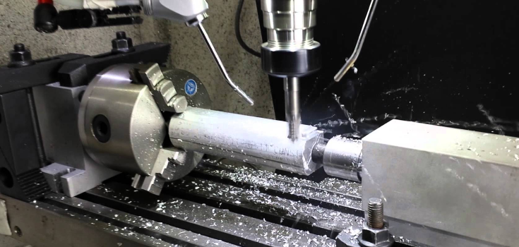
CNC milling is a subtractive manufacturing process in which a computer-controlled, rotating cutting tool removes material from a solid block (called a workpiece or blank) to produce a part with precise dimensions and complex geometry. It's the most widely used machining process for turning digital designs into functional metal and plastic parts, from simple brackets to multi-axis aerospace housings. Choosing it over turning, casting, or 3D printing comes down to geometry, tolerance, and volume; the sections below cover how the process runs, what machines and operations it relies on, which materials it cuts well, and where its real limits are.
What Is CNC Milling?
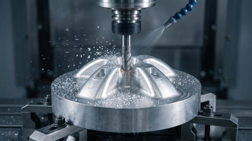
CNC milling is a machining process where a spinning cutting tool, mounted on a motorized spindle, moves across or into a stationary (or slowly moving) workpiece to cut away material and reveal the finished shape. "CNC" stands for Computer Numerical Control: a computer program directs every movement of the tool and the worktable, which is what separates modern milling from manually operated mills and gives it its repeatability across large production runs. A properly programmed and tooled setup can hold tight positional and dimensional tolerances part after part, which is the main reason it's specified for anything that needs to fit or seal reliably against a mating component.
It's easy to confuse milling with turning, since both fall under CNC machining as an umbrella term. The distinction is simple: in milling, the cutting tool rotates and the workpiece is typically held still or moved slowly beneath it; in turning, the workpiece itself spins on a lathe while a stationary tool cuts into it. That difference in kinematics is why milling excels at flat faces, pockets, slots, and irregular 3D contours, while turning is the natural choice for round, symmetrical parts like shafts and bushings. If your part geometry sits somewhere between the two, CNC Milling Vs CNC Turning breaks down how to decide based on your specific features.
How Does CNC Milling Work? The CNC Milling Process
Every milling job (regardless of machine size or part complexity) follows the same sequence from digital design to finished part.
- CAD modeling. The part starts as a 3D model built in CAD software, with dimensions, tolerances, and material called out on the drawing or model annotations.
- CAM programming. CAM software converts the 3D model into G-code: a set of numerical instructions that tell the machine exactly where the spindle and worktable need to move, at what speed, and at what depth. This is the step where the geometry on screen gets translated into a machine-readable toolpath, including roughing passes, finishing passes, and tool-change sequences.
- Machine setup and workholding. An operator mounts the correct cutting tool in the spindle, clamps or fixtures the workpiece securely to the worktable (using a vise, fixture plate, soft jaws, or vacuum chuck depending on the part shape) and sets the work coordinate origin so the machine knows exactly where the part sits in space.
- Cutting execution. The machine runs the program, moving the spindle and table along programmed axes while the rotating tool removes material in a series of passes. Roughing cuts remove the bulk of the material quickly at the expense of surface finish; finishing passes run slower and shallower to hit the final dimension and surface texture called out on the drawing.
- Post-processing. Parts are deburred, inspected against the drawing (often on a coordinate measuring machine (CMM) for critical dimensions) and sent for any secondary finishing such as anodizing, plating, or powder coating before shipping.
Feed rate, spindle speed, and depth of cut are adjusted throughout the program based on the material being cut and the tool in use; harder materials and larger-diameter tools generally run slower to avoid excessive tool wear or chatter. Getting these parameters wrong is one of the more common causes of scrapped parts, which is why CAM programming and tool selection are treated as engineering steps, not just data entry.
Types of CNC Milling Machines
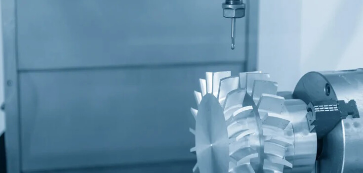
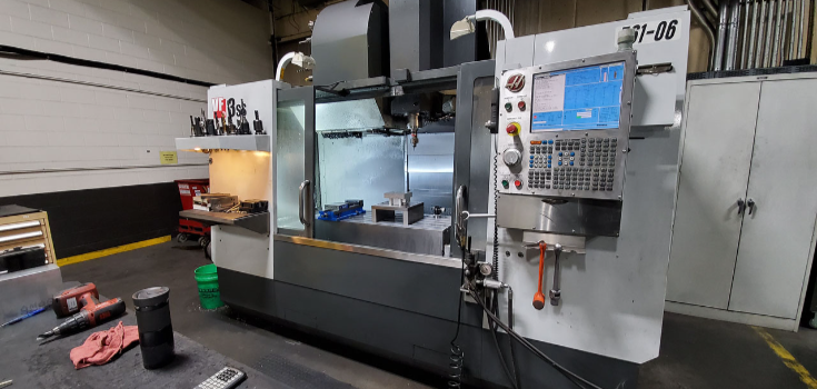
A CNC milling machine (also called a machining center) holds the cutting tool in a spindle above or beside a worktable that carries the workpiece. Machines are broadly split into vertical machining centers, where the spindle axis is vertical and the tool plunges down into the part (the more common configuration for general-purpose work) and horizontal machining centers, where the spindle axis runs horizontally, which tends to suit heavier parts and multi-sided machining without repositioning between operations.
Within either configuration, the number of axes the machine can move determines what geometry it can reach in a single setup:
- 3-axis machining moves the tool along X, Y, and Z: straightforward, cost-effective, and well suited to flat and stepped geometry.
- 4-axis machining adds a rotational axis so the part (or tool) can turn during the cut, reaching features on multiple faces without re-fixturing.
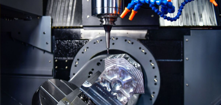
- 5-axis machining adds a second rotational axis, allowing simultaneous tool and part movement across five axes.
The extra axes pay off once a part has features on multiple faces or curved surfaces that a 3-axis setup would need several fixture changes to reach; each re-fixturing step adds handling time and reintroduces the risk of alignment error, so consolidating those operations into one 4- or 5-axis setup often costs less overall even though the machine time runs higher. For the tilt-angle mechanics and setup strategy behind each configuration, see 3-Axis CNC Machining, 4-Axis CNC Machining, and 5-Axis CNC Machining, or Vertical vs Horizontal Milling Machines for how the two machine layouts compare on rigidity and part size.
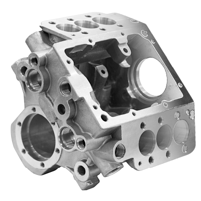
Machine size also matters for larger parts: structural components and large housings that run up to roughly 1000 mm in a single dimension need worktables, spindle travel, and fixturing rated for that envelope, which is a separate consideration from axis count.
Common CNC Milling Operations
Different features on a part call for different milling operations, each paired with a specific cutter geometry.
- Face milling cuts flat surfaces by engaging the end and side edges of the tool, using face mills to remove material quickly across a wide area; this is usually the first operation on a new blank to establish a flat reference surface.
- Plain (slab) milling uses a cylindrical cutter with teeth on its circumference to cut flat surfaces parallel to the cutter's axis: one of the most basic operations, still used for simple stock reduction.
- Angular milling produces angled surfaces and tapers by feeding a cutter into the workpiece at an angle other than perpendicular, useful for chamfers, dovetails, and wedge-shaped features.
- Form milling uses a specially profiled cutter to produce contoured, curved, or irregular shapes, such as keyways or decorative profiles, in a single pass rather than multiple straight cuts.
- Slot milling cuts narrow, straight-sided grooves into a workpiece; the depth-to-width limits, cutter selection, and when a dedicated slot cutter beats a standard end mill are covered in What is Slot Milling: Process.
- End milling is the most versatile operation, using an end mill to cut pockets, slots, contours, and profiles in almost any direction; see End Milling 101: Process for how it differs from face milling and when each is the better choice.
Most of these operations rely on just two families of cutting tools: end mills (side- and bottom-cutting, used for slots and pockets) and face mills (wide-diameter cutters used for flat surfacing). Tool material (carbide, high-speed steel, or coated variants) is chosen based on the workpiece material and how much material needs to come off; carbide holds up better in hard alloys but costs more per tool, which is a tradeoff programmers weigh against expected tool life on a given job.
Materials Used in CNC Milling
CNC milling cuts both metals and engineering plastics, which is part of why it's specified across so many industries. Machinability, achievable surface finish, and cutting speed all vary significantly by material family, which affects both cycle time and cost.
| Material Family | Common Grades Machined | Typical Use Case |
|---|---|---|
| Aluminum | 6061, 6063, 5083, 5052 | Lightweight housings, brackets, heat sinks |
| Stainless & Alloy Steel | 316LVM, 17-4PH, 4140, 4340, 8620 | Structural parts, fasteners, fit-critical assemblies |
| Titanium | Ti-6Al-4V | Aerospace structure, medical implants |
| Brass & Copper | 260, C360, C101, C110 | Electrical contacts, fittings, decorative parts |
| Superalloys | Inconel (incl. 718), Invar | High-temperature and low-expansion applications |
| Engineering Plastics | PEEK, PTFE, Delrin, Nylon, PC | Low-friction, chemically resistant, or insulating components |
DEK machines 50+ metals and engineering plastics for production parts, so material availability is rarely the limiting factor on a given job; the bigger questions are usually tolerance, wall thickness, and finish requirements for the specific alloy or polymer in play. Hard-to-machine materials such as Ti-6Al-4V, Inconel 718, 17-4PH, and PEEK need slower cutting speeds and more frequent tool changes, which is reflected in longer cycle times rather than in the material itself being unmachinable.
Applications of CNC Milling
CNC milled parts show up wherever tight tolerances and repeatable geometry matter:
- Aerospace: structural support parts and cabin interior components that need documented traceability and dimensional consistency across a production run.
- Medical devices: device housings and instrumentation components machined to biocompatible material specs and tight fit tolerances.
- Robotics: joints, brackets, and end-effector components where weight, stiffness, and repeatability all matter simultaneously.
- Semiconductor equipment: components requiring very tight flatness and positional tolerances, often in specialty materials like Invar or stainless steel.
- Industrial equipment and automation: housings, mounts, and structural components for machinery that runs continuously under load.
- Automotive: brackets, housings, and prototype components produced ahead of tooling for stamped or cast production parts.
What ties these industries together is a need for parts that hold dimension across a production run, not just on the first piece off the machine, which is why quality documentation (first article inspection, in-process checks, final inspection) travels alongside the parts, not as an afterthought.
Advantages of CNC Milling
- Precision and repeatability. Once a program is proven, every part in the run follows the same toolpath; dimensional variation comes down to tool wear and machine calibration, not operator judgment call by call.
- Material versatility. The same machine, with a tool change and updated cutting parameters, can move from aluminum to stainless steel to PEEK without retooling the whole process.
- Geometric versatility. Flat faces, pockets, slots, curved surfaces, and threaded holes can all come from one setup, especially on 4- and 5-axis equipment that reaches multiple faces without re-fixturing.
- Reduced human error. Automation removes the manual feed-and-speed judgment calls that introduce variation in hand-operated milling, which matters most on tight-tolerance or safety-critical parts where a missed dimension isn't an option.
- Fast iteration on design changes. Because the process is program-driven, a revised CAD model can usually be re-programmed and re-cut without new tooling, which is why milling is a common choice for both prototypes and the production parts that follow them.
Disadvantages and Limitations of CNC Milling
CNC milling isn't the cheapest or fastest option for every job. Programming, fixturing, and tool setup take time regardless of part quantity, so a single prototype carries the same setup burden as the first part of a production run; the setup cost only gets diluted as quantity increases. Cutting tools wear faster in hard materials like titanium and hardened tool steel, which drives up cycle time and tooling spend on those jobs specifically.
Some geometries are difficult or impossible to reach with a rotating tool, even with 5-axis capability. Deep, narrow cavities with a high depth-to-diameter ratio limit tool rigidity and chip evacuation, sharp internal corners can't be cut with a round tool without leaving a radius, and certain undercut features simply sit outside the reach of any rotating cutter regardless of axis count. Those features are sometimes better suited to a different removal process entirely, or to a design revision that adds a corner radius or splits the feature into a separate operation.
Designing Parts for CNC Milling: Common DFM Fixes
Most cost and scrap issues on a milled part trace back to a handful of design choices that are easy to catch before the program is written:
- Sharp internal corners. A rotating end mill can't cut a true sharp internal corner; it leaves a radius equal to the tool radius. Specifying a corner radius that matches an available tool diameter avoids a slower, smaller tool or a manual finishing step.
- Thin walls. Walls that are too thin relative to their height can deflect under cutting force, leading to chatter marks or out-of-tolerance surfaces. Adding wall thickness or bracing ribs where possible reduces both scrap risk and cycle time.
- Deep, narrow pockets. A pocket that's much deeper than it is wide forces the use of a long, thin tool that flexes more and cuts slower. Opening up the pocket width or breaking the feature into stages keeps tool deflection manageable.
- Over-tight tolerances on non-critical features. Every tolerance tighter than the part actually needs adds inspection time and slows the finishing pass. Reserving tight tolerances for fit-critical dimensions and relaxing the rest keeps cost proportional to what the part actually requires.
- Tolerance stacking across mating features. When several toleranced dimensions compound across an assembly, small individual tolerances can add up to a fit problem. Reviewing the stack-up before machining catches this earlier and cheaper than catching it during assembly.
Catching these issues at the design stage (rather than after a batch has already been cut) is usually the single biggest lever for controlling both scrap rate and per-part cost on a milling job.
How Much Does CNC Milling Cost?
CNC milling cost depends on the material being cut, part complexity and feature count, tolerance requirements, order volume, and any secondary finishing. Setup (programming, tool selection, and workholding) is a largely fixed cost per job, so it weighs most heavily on small orders; a single prototype absorbs the full setup cost by itself, while a batch of 100 spreads that same setup across many more parts, and a run of 1,000 or more amortizes it further still, which is why per-part price typically drops fastest between a one-off and a modest batch and levels off at higher volumes. Harder materials and tighter tolerances add cutting and inspection time regardless of quantity, which is why two parts with the same geometry but different materials rarely cost the same.
For a full breakdown of how each of these factors moves the price on a specific job, see the CNC milling cost breakdown.
Get Your CNC Milled Parts Made
DEK machines CNC milled parts from prototype through production on 3-, 4-, and 5-axis equipment, holding tolerances as tight as ±0.005 mm on general work and down to ±0.003 mm on micro-precision components, with no minimum order quantity. The shop operates under ISO 9001, ISO 13485, and AS9100D certification, which matters if your parts are headed into medical devices or aerospace hardware where documentation and traceability aren't optional.
If your part needs holes rather than pockets or contours, CNC Drilling: Types and Applications is worth understanding on its own terms, and Difference Between CNC Milling And CNC Drilling explains when each is the right call for a given feature. When you're ready to get a quote on a design, contact DEK's team with your drawing and material spec, or go straight to CNC Milling Services to see what's involved in getting a part started.
Frequently Asked Questions
What is milling in CNC?
CNC milling is a subtractive process where a computer-controlled, rotating cutting tool removes material from a workpiece to create a part's final shape. The "CNC" part means a program (not a human operator) controls the exact speed, depth, and path of every cut, which is what makes results repeatable across a full production run rather than just on one piece.
How much does it cost to get something CNC milled?
Cost depends on material, part complexity, tolerance, order volume, and finishing; there's no flat rate that applies across jobs. A simple aluminum bracket in a batch of 100 costs far less per part than a tight-tolerance titanium component made as a single prototype. Contact DEK with your drawing for a project-specific quote.
What are the downsides of CNC milling?
Setup and programming take a fixed amount of time regardless of order size, which makes very small runs less cost-efficient than higher-volume batches. Hard materials wear cutting tools faster, and certain deep, narrow, or undercut geometries are difficult to reach with any rotating cutter, no matter how many axes the machine has.
What is milling used for?
Milling produces precision parts across aerospace, medical devices, robotics, semiconductor equipment, industrial automation, and automotive applications, anywhere a part needs tight tolerances, repeatable geometry, and a choice between metal or plastic material within the same manufacturing process.
What's the difference between CNC milling and CNC turning?
In milling, a rotating tool cuts a stationary or slowly moving workpiece, which suits flat faces, pockets, and irregular contours. In turning, the workpiece itself rotates against a stationary tool, which suits round, symmetrical parts like shafts and bushings. See CNC Milling Vs CNC Turning for a full comparison.
Can CNC milling cut wood?
Yes: milling as a general process can cut wood, plastic, and metal, since the underlying mechanism of a rotating cutter removing material works across all three. Precision CNC machining shops focused on industrial and medical parts typically work in metals and engineering plastics rather than wood, since that's where tight-tolerance production parts are needed.
WRITTEN BY
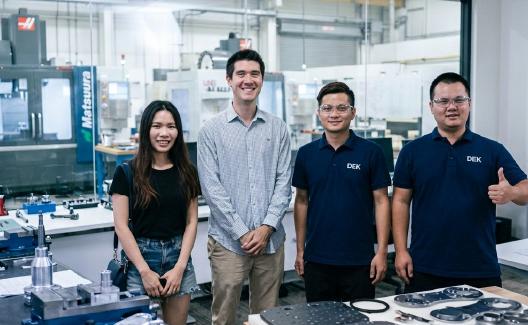
Bing manages daily production, covering scheduling, workflow coordination, and shop-floor control. He has strong experience in machining processes, tooling, and practical problem-solving. In his free time, he likes outdoor exploration and adventure trips.
Related Posts
-
 Shear Stress: All You Need to Know
-
 Guide To In-Mold Labeling (IML): Everything You Need To Know
-
 Melting Point of Iron: Informative Guide
-
 Liquid Silicone Rubber: Properties, Types, and Process
-
 Melting Point of Magnesium: Informative Guide
-
 Nickel Melting Point: A Detailed Guide
-
 Properties of Metalloids: Informative Guide
-
 All You Need to Know about Wire Cut EDM
-
 What is a Grinding Machine : Components, Types, and Uses

Ready to Scale Your Project?
Get started with a stable process and controlled quality. Let's discuss your project.