
Why 2D Drawings are Important When Ordering Custom CNC Parts?
Production errors often happen when clear documentations are not processed when ordering custom CNC parts. That is the reason why understanding 2D drawings is not just optional but a must. Understanding it is practical as a detailed drawing presents requirements, tolerances, finishing notes, and intent in a way verbal discussions can't.
Even in the presence of a 3D drawing, we rely on 2D for specifications. This is where we avoid misinterpretations and create a detailed technical reference before machining.
What are 2D Drawings?
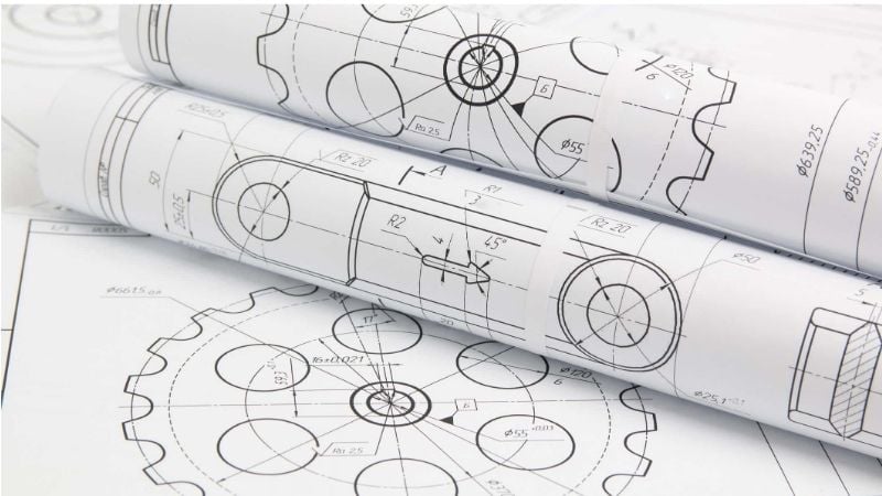
A 2D drawing is a flat drawing that defines its geometry using section cuts, tolerances, dimensions, surface finish, and manufacturing notes. While the 3D model presents itself visually, 2D drawings are made like measurable instructions and specifications, such as material grades, inspection points, hole depths, geometric dimensions, tolerances, and many others.
In machining setups, this document becomes the main reference because a particular feature should be defined on the 2D drawings before it can be guaranteed in production.
Why 2D Drawing is Important When Ordering Custom CNC Parts?
Critical Features
Some features in a CNC part require extremely tight tolerances. These can include bearing seats, precision holes, threaded sections, and alignment surfaces.
Portability
The convenience of a 2D drawing being printable and easy to share without using specialized CAD software makes it a practical choice. Easy access provides us with the ease to be on the same page with the team working on production.
Familiarity
2D drawings have a reputation for being intuitive because of their decades of workplace and production practice. Technicians prefer a drawing even when 3D models are available because it is a language they are familiar with.
Annotations
Everything can be noted in terms of tolerances, heat treatment, threads, and finish. This guides production. But annotations work on the things that geometry cannot, and this helps in preventing misinterpretations that lead to errors.
Verification
The drawing is often the official reference, and quality control relies on it. Quality checks on finished parts are measured based on what is documented and not on a visual model.
Additional Information
The organized approach to having material, coating, assembly instructions, and revision history in one drawing makes consolidating easier. It keeps the production aligned with the requirements and prevents miscommunication.
Essential 2D Drawing Formats to Provide When Ordering Custom CNC Parts
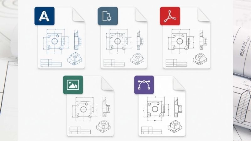
DWG (AutoCAD Drawing)
The industry standard in AutoCAD is the DWG files. They keep the notes exactly as designed and preserve layers and dimensions. They can be referred to directly, and that minimizes assumptions and reduces errors.
DXF (Drawing Exchange Format)
DXF makes it convenient even when a different CAD software is involved. We can work accurately even without AutoCAD because they carry essential details and geometry.
PDF (Portable Document Format)
PDFs are handy for quick reviews, sending to the team, and approvals because they are simple to share and open on any device.
TIFF (Tagged Image File Format)
TIFFs are not often used for CNC programming, but are still helpful as a reference. They keep drawings clear and sharp when archiving or printing.
SVG (Scalable Vector Graphics)
SVGs are useful for presentations, visual verification, and online project portals. Even modern workplaces use them to do simple geometry verifications.
Key Elements of CNC 2D Drawings

Design Reference
A reference point of a drawing shows relevant notes that set the tone of the entire design. It is the starting point of a drawing that also presents the intended orientation and part number, which helps keep track of the component being produced.
Geometry and Dimensions
The foundation of a design is the size and shape. The outlines, views, holes, and measurements are the reference that a part can be cut and milled accurately. Dimensions that are not clear usually cause errors.
Tolerances and Specifications
Details like measurements, though it doesn’t need to be exact, and tolerances define limits that are acceptable. These factors prevent issues with fit and functions once assembled.
Material Information
The drawing must state the material grade, type, and treatment to be used. Wrong material choice compromises performance and surface finish.
Machining Instructions
The notes bridge the gap between the practical steps and intent. So the guide in terms of cutting speed, milling, drilling, and finishes is a great help during production.
Assembly Information
If the component is a part of a bigger setup, assembly instructions clarify orientation, location, and surfaces. This prevents errors that may occur in the future.
Controllo qualità
To ensure the final result matches the specifications, necessary checks are needed. In drawings, they indicate testing requirements, dimensions, and inspection points.
Practical Tips to Follow When Providing 2D Drawings for Your Custom CNC Parts
Submit both a CAD Model and a 2D Drawing
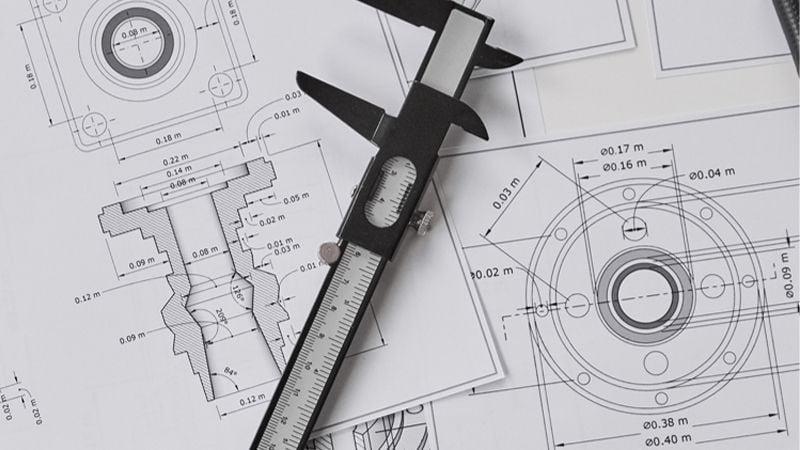
Based on experience, it is not safe to rely on just one file because the two have their own purposes. 2D drawing specifies tolerances, dimensions, and notes, while a CAD model defines the 3D form. When used together, they give us measurable instruction and a visual idea.
Use Drawings to Specify Tolerances
We tend to rely on default general standards when tolerances are not clearly stated. It does work, but only applicable for non-critical parts. As for functional components, they need defined limits. Stating critical details matters a lot to avoid overtolerance.
Following Drawing Standards
When units, symbols, and formatting are all consistent, it prevents confusion on our end. Whether we use ASME or ISO, we choose to stick to a recognized system to understand and to avoid guessing.
Keep Drawings Clear and Simple
Complicated drawings send the wrong interpretation. Avoid stacking unnecessary dimensions. Whenever you can, simplify things to make it cleaner and easier to interpret. A clear drawing prevents mistakes compared to complicated details.
Review Before Sending
Avoid expensive rework by doing internal checks before sending. This confirms critical factors, like if the material notes match the CAD model, whether the dimensions are complete, and whether the revision numbers tally.
CNC 2D Drawings vs 3D Models
CNC 2D drawings and 3D models may present the same part, but they serve different functions. A 3D model helps visualize how each feature relates in terms of space and geometry, and this is helpful during toolpath generation.
The 2D drawing, on the other hand, defines the mandatory details like material, tolerances, dimensions, and surface demands. We rely on the model for the applicable strategy, but always check the drawing to confirm other limits and criteria. The bottom line is, the other explains form, and the other focuses on the intent in a measurable sense.
Conclusione
Uncertainty in custom CNC production is reduced by clear 2D drawings. It helps prevent delays and revisions when tolerances, dimensions, materials, and inspection criteria are defined before the start of production. A precise 2D drawing also improves communication and results in more predictable outcomes.
DEK delivers reliable results and partner teams that expertly understand the standards and realities of applying drawings in manufacturing. Contattateci today so we can review your files and move forward with confidence and clarity.
