Guía
Guías claras, enfocadas en ingeniería, sobre procesos de mecanizado, selección de materiales, tolerancias y fabricabilidad.
Tipo de tema
Procesos
Industrias
1 - 15 of 444 Posts
Top 10 Applications of Kovar: An Informative Guide
You often work with components that must stay dimensionally stable under heat, pressure, or vacuum. […]
por Roberto Lee -
5 Mar 2026
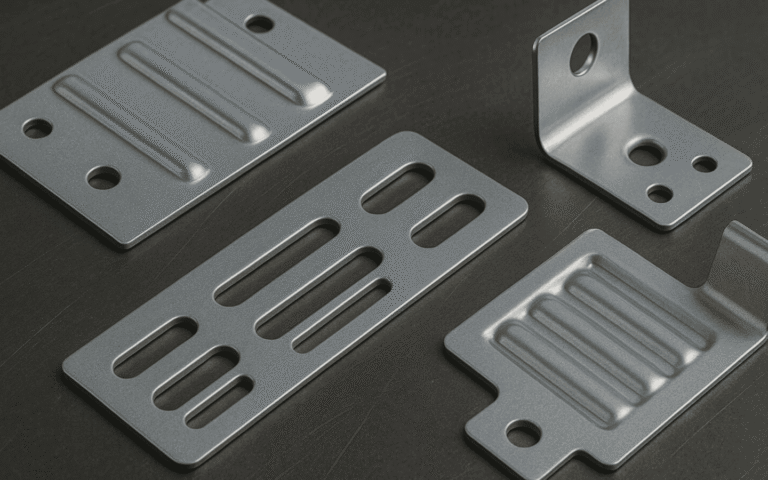
Sheet Metal Part Drawings: Design and Fabrication Guidelines
Sheet metal drawings show how and what to do to fabricate any type of sheet […]
por Kim -
9 Ene 2026
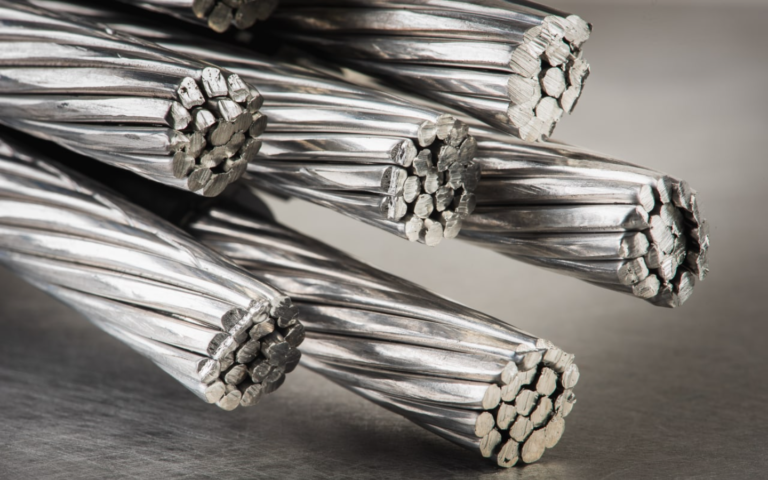
Electrical Conductivity of Aluminum: A Complete Guide
Aluminum is one of the important metals due to its lightness, stability, and high electrical […]
por Roberto Lee -
2 Dic 2025
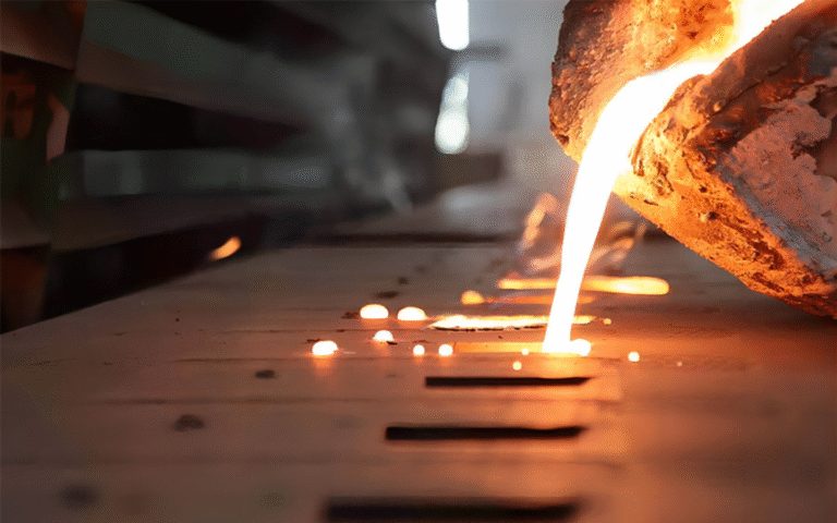
Melting Point of Magnesium: Informative Guide
When you work with metals, it’s important to know how they react to heat. The […]
por Roberto Lee -
27 Oct 2025
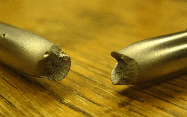
What is Brittleness: A Complete Guide
Brittleness is an essential material property that changes design, manufacturing, and product strength. When a […]
por Ryan Zhou -
8 Oct 2025
Aluminum Gears: A Complete Guide
Aluminum gears are popular due to their good balance of light weight, strength, and smooth […]
por Roberto Lee -
6 Oct 2025
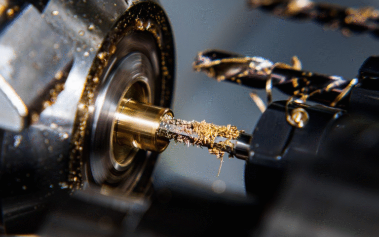
CNC Machining Brass: An Ultimate Guide for Precision Manufacturing
CNC machining brass is a great option when you need high-quality, precise parts. Brass is […]
por Roberto Lee -
8 Sep 2025
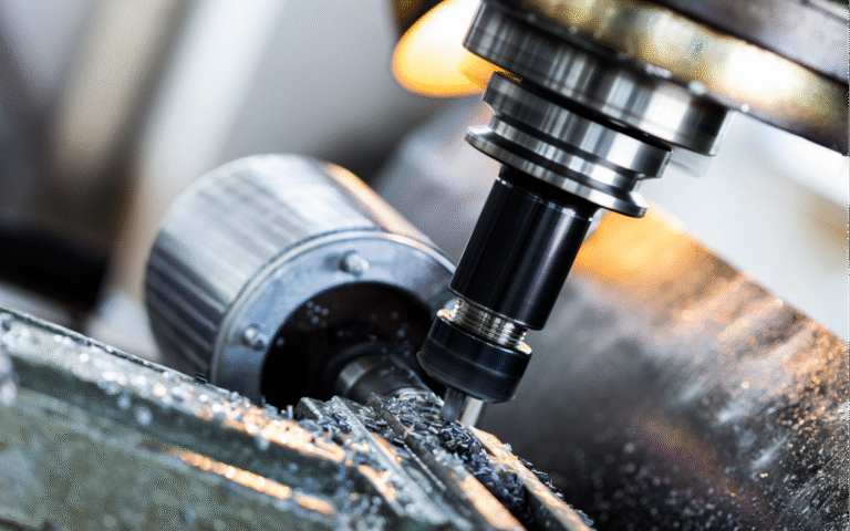
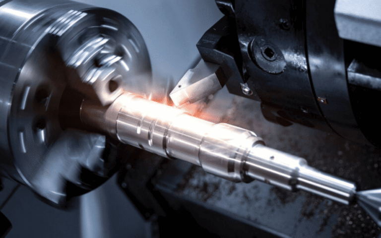
CNC Machining Aluminum: A Simple Guide for Custom Aluminum Parts
When you need strong and light custom parts, you can opt for CNC machining aluminum. […]
por Roberto Lee -
4 Sep 2025

How to Achieve Precision in Medical Parts: Informative Guide
When you make medical parts, you need to be very exact because a small mistake […]
por Ryan Zhou -
16 Ago 2025
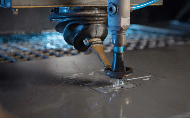
Boquillas de corte por chorro de agua: Guía completa
If you work with waterjet cutting, you know how important the nozzle is. It directs […]
por Bin Fan -
31 de julio de 2025
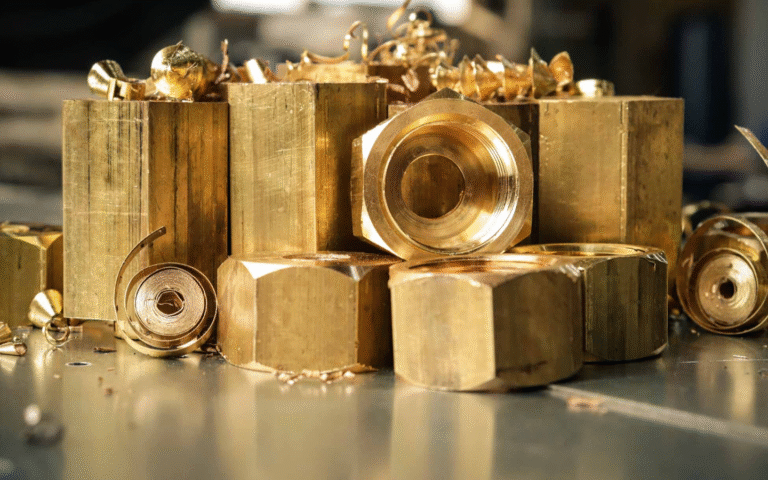
¿Se oxida el latón? Guía informativa
You might be asking, does brass rust? It’s a good question because rust can cause […]
por Roberto Lee -
28 Jul 2025
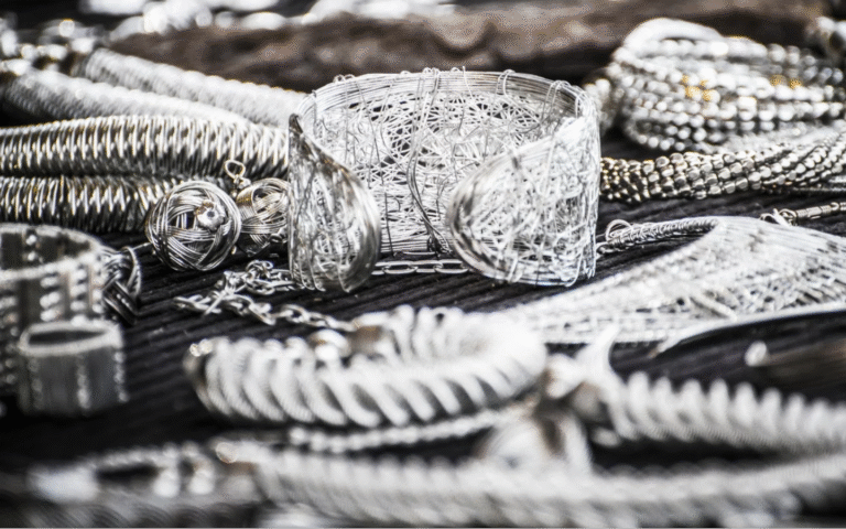
Densidad de la plata: Una guía completa
When you work with silver, you need to understand its basic properties. One important property […]
por Roberto Lee -
26 Jul 2025
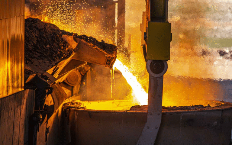
Punto de fusión del hierro: Guía informativa
Iron is a strong metal that you use in many things, like buildings, machines, and […]
por Roberto Lee -
25 Jul 2025
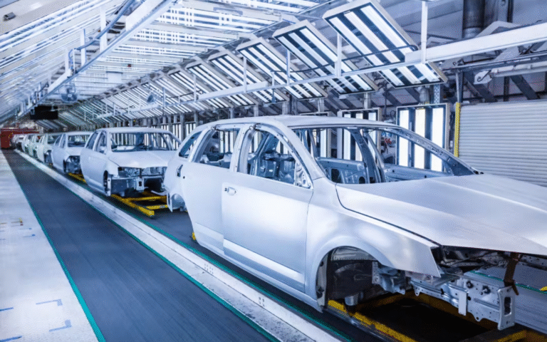
Fabricación de chapa metálica para automoción: Guía completa
If you build or work on cars, you know how important metal parts are. Most […]
por Kim -
22 jul 2025
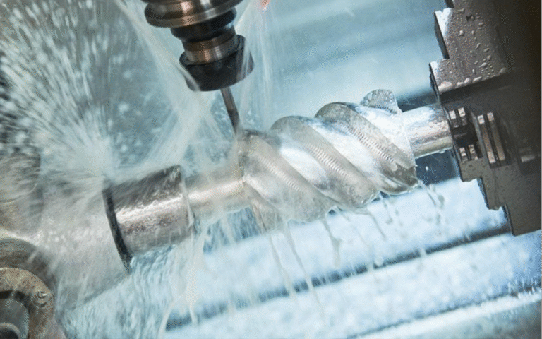
Fresado helicoidal: Una guía útil
One of the modern machining processes that gained attention over the years is helical milling. […]
por Kim -
12 jul 2025