What is Straightness in GD&T: Basic Concepts
In Geometric Dimensioning and Tolerancing (GD&T), straightness is an important rule. It makes sure that a surface or an axis does not bend too much from a straight line. Understanding what straightness is in GD&T helps you make better parts and ensures they fit and work correctly.
What is Straightness in GD&T?
Straightness is a symbol in GD&T that ensures a part or surface is not bent or curved. It checks how straight something is.
You can use straightness in different ways in engineering. GD&T straightness examples are the following:
- A table needs to be straight (or flat—you’ll learn the difference soon) so objects don’t wobble or roll off.
- The inner ring of a bearing must be very straight along its length to fit properly on a shaft. If it isn’t straight, the bearing can be misaligned and get damaged.
Straightness Callout and Symbol
The straightness symbol looks like a flat, horizontal line (a dash). You will see this callout on either a surface or a feature of a size.
One key thing to remember is that straightness in GD&T does not depend on a reference point (datum), unlike other symbols like parallelism.
Why Straightness Matters in CNC Machining?
Straightness is very important in manufacturing and engineering. Even small mistakes can cause big problems when putting parts together or making them work correctly. If parts need to fit tightly or spin smoothly, keeping them straight helps avoid misalignment, damage, or failure.
It also helps with quality control; it makes sure parts meet the right standards and work as they should.
Surface Straightness in GD&T
Surface straightness applies to flat or cylindrical surfaces. It controls how much a surface can vary along a straight 2D line. On a flat surface, this line can be anywhere. On a cylinder, the line runs parallel to the axis.
Surface straightness does not apply to the entire shape of a part. Instead, it only controls the straightness of the reference surface.
How to Measure Surface Straightness?
Checking surface straightness requires precise tools and skilled operations. There are two main ways to measure it.
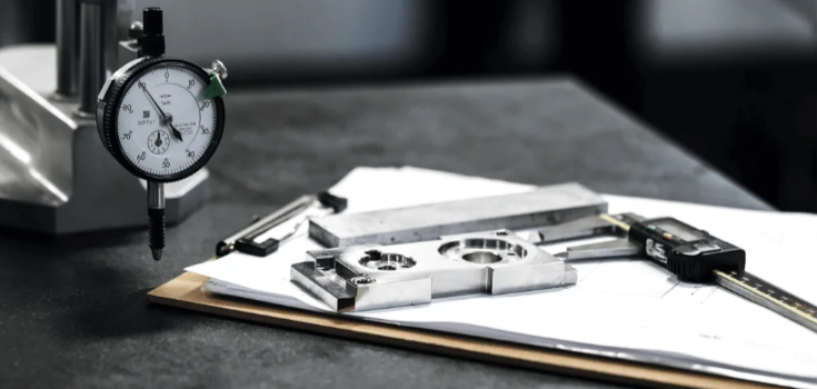
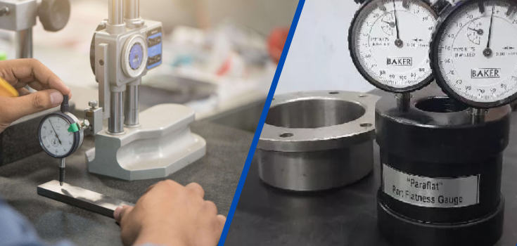
Using a Dial Gauge (Height Gauge)
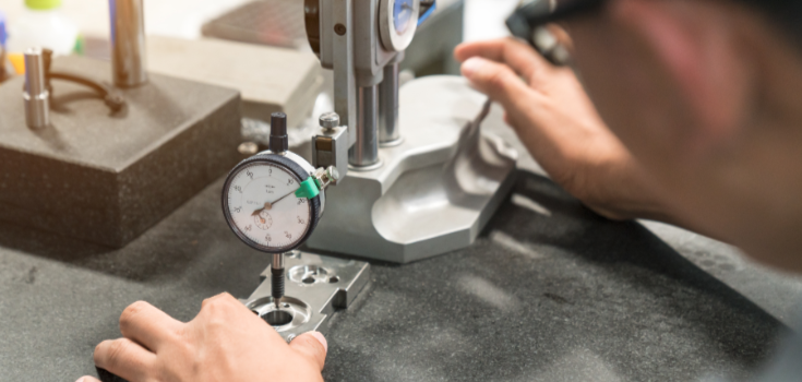
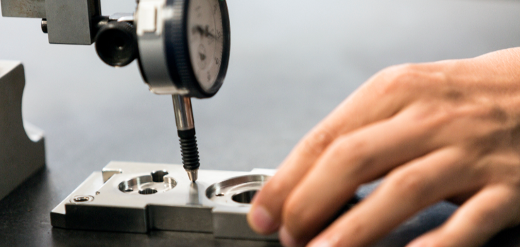
A dial gauge is a common tool for manually checking straightness. If the variation stays within the allowed limit, the part passes inspection. Here’s how it works:
- Secure the gauge properly.
- Place the dial’s contact point against the surface.
- Slide it along the 2D measurement line.
- Make sure the dial is calibrated, set to zero, and slightly pressed in before starting.
Using a Coordinate Measuring Machine (CMM)
A CMM provides more precise and automated measurements. CMMs are more accurate than dial gauges and eliminate human error. The process:
- Mount the part on the CMM bed.
- The probe scans the surface along the measurement line.
- The machine generates a report showing if the part meets the tolerance.
Straightness on Derived Median Line in GD&T

The derived median line (DML) is an imaginary centerline of a part that has a symmetric shape, like a cylinder. In GD&T, when you apply a straightness tolerance to the DML, you are making sure this centerline stays straight within a certain limit.
This tolerance creates a perfect cylindrical zone around the true centerline of the part. It helps detect twists, bends, and other shape problems.
One unique thing about straightness in this case is that it does not require a datum (a reference feature for measurement). Many GD&T symbols, like perpendicularity, need a datum to compare against. But straightness does not—it only focuses on the feature itself.
MMC/LMC Callout
Sometimes, straightness is used with the Maximum Material Condition (MMC) modifier (Ⓜ). MMC means the part has the most material possible. For a shaft, this happens when it is at its largest allowable diameter. The goal of using MMC is to make sure the part still fits properly, even when it is slightly out of shape.
In the case of a shaft. The straightness tolerance affects how the part fits into a gauge (a measuring tool). The formula for checking this is:
Gauge Cylinder ID = Max Ø part (MMC) + Straightness Tolerance
Например:
- If the maximum shaft size is 10.05 mm
- And the straightness tolerance is 0.03 mm
- The gauge hole size would be 10.08 mm
Bonus Tolerance
When the part is smaller than the maximum allowed size, it gets an extra tolerance called bonus tolerance. This concept helps manufacturers build parts with more flexibility while still keeping quality in check.
Например:
- If the shaft is 10.03 mm instead of 10.05 mm, that extra 0.02 mm (10.05 – 10.03) is added to the straightness tolerance.
- If the original straightness tolerance was 0.03 mm, it now becomes 0.05 mm (0.03 + 0.02).
How to Measure the Straightness of a Derived Median Line?
To check the straightness of a DML, engineers use different methods:
Cylindrical Gauge
This is the most common. A hole is used as a gauge. If the part fits inside without resistance, it meets the straightness requirement. This is a quick and reliable way to check straightness. In most cases, using a gauge is enough to ensure that the part meets straightness requirements.
CMM (Coordinate Measuring Machine)
This method checks the centerline position at different points. It is more precise but slower and is used only when necessary.
Feature Control Frame (FCF) of Straightness
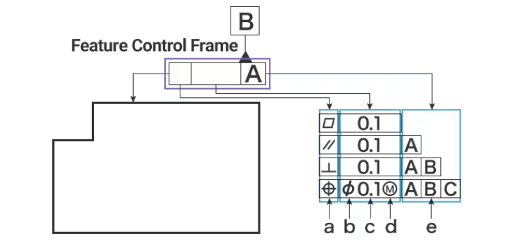
The feature control frame (FCF) gives you all the details about the tolerance.
Surface Straightness FCF
For surface straightness, the first part of the FCF contains the straightness symbol, which looks like a short horizontal line (similar to a hyphen).
The second part shows the tolerance value and any material modifiers (like maximum material condition) if needed. Since the tolerance zone is a total wide zone, no extra symbols are required because this is the default setting.
You don’t need a datum for straightness. The leader arrow simply points to the surface that needs to be controlled.
Axis straightness FCF
For axis straightness, the FCF looks almost the same, but there is an extra symbol for the type of tolerance zone. Since the tolerance zone is a cylinder, the second part of the FCF includes a diameter symbol to show this.
Another key difference is that instead of making a surface, the leader arrow points to the part’s size dimension. This tells you that the straightness control applies to the center axis of the part, not just the surface.
Straightness vs Flatness: What are the Differences?
Flatness and straightness in GD&T are very similar, which often causes confusion. This section will explain the difference in a simple way:
- Flatness applies to an entire surface, while straightness only controls a single line.
- Flatness controls a 3D surface, while straightness applies to a 2D line.
- Flatness is only used for flat surfaces, and the whole surface must stay within the allowed tolerance. Straightness can apply to lines, edges, axes, and centerlines, giving designers more flexibility.
Straightness vs Profile of a Line
A profile of a line can act like a straightness rule when used on a surface. But be careful—if you apply it using datums, it will also control the position and angle of the surface, not just its shape.
Straightness is a simple rule that only checks if something is perfectly straight, without any other restrictions. Profile of a line is stricter and can be more expensive because it might require special measuring tools.
For most engineers, checking straightness on its own is easier to understand and use. Think about what you really need from your inspection and make sure your drawings match those needs.
Applications of Straightness in Manufacturing

Below are some examples where straightness is used in manufacturing and its application in different industries.
Keeping Surface Straight
If you weld a steel bar in a T-shape to another bar, checking for straightness helps keep the surface even at the weld. This prevents problems that could lead to costly fixes.
Keeping the Center Axis Straight
For round parts, like shafts or cylinders, keeping the central axis straight is key to making sure they fit and work properly. Even when a part is at its largest allowed size, it still needs to fit into the space it’s designed for.
Аэрокосмические детали
In aircraft, every component must be as straight and precise as possible. Following strict straightness rules ensures that parts fit and function properly, keeping planes safe and reliable.
Медицинские приборы
Medical equipment must be built with extreme precision so that parts fit together perfectly and work safely. Straightness helps ensure that these devices function as intended, which is crucial for patient safety.
Обработка с ЧПУ
Companies like DEK focus on straightness in their обработка process. This helps them create high-quality products, reduce errors, and keep customers satisfied.
Assembly in Manufacturing
When parts are perfectly straight, putting them together is easier. In the car industry, for example, well-aligned parts make assembly simpler and improve overall performance. By following strict straightness rules, manufacturers ensure that everything fits and works correctly.
Comparison with Other GD&T Tolerances
Here’s a useful comparison table of GD&T Tolerances:
| Geometric Category | Tolerance Type | Описание | Символ | ASME Section |
| For Individual Features | Форма | Прямолинейность | ─ | 6.4.1 |
| Плоскость | ⏥ | 6.4.2 | ||
| Circularity | ○ | 6.4.3 | ||
| Individual or Related Features | Profile | Line Profile | ⌒ | 6.5.2(b) |
| Surface Profile | ⌓ | 6.5.2(a) | ||
| For Related Features | Ориентация | Angularity | ∠ | 6.6.2 |
| Перпендикулярность | ⊥ | 6.6.4 | ||
| Параллелизм | // | 6.6.3 | ||
| Расположение | Позиция | ⊕ | 5.2 | |
| Концентричность | ◎ | 5.11.3 | ||
| Симметрия | ⌯ | 5.13 | ||
| Runout | Circular Runout* | ↗ | 6.7.1.2.1 | |
| Total Runout* | ⌰ | 6.7.1.2.2 |
*Arrows may be filled or not filled*
Заключение
Straightness is an important part of GD&T in engineering. It helps manufacturers understand the design and tolerance requirements and applies to different geometric features.
На сайте DEK, our engineering team has experience with many manufacturing processes. We create test parts that match final products using custom CNC machining, rapid tooling, and more. We can also review your engineering drawings to make sure they meet production standards before prototyping or manufacturing. Contact us today for a free quote and start your next project!
Вопросы и ответы
Where can straightness be applied?
Straightness controls how much a surface can vary along a 2D line. Since this line is on the surface, it also affects the surface itself. If you need to control the entire flat surface in 3D, you can use the flatness symbol instead, if possible.
What standards apply?
The ASME Y14.5 standard is the main guide for GD&T, including the straightness symbol. It explains how the symbol works, how to use it, and how to apply it correctly.
What is bonus tolerance?
Bonus tolerance gives you extra tolerance when the straightness symbol includes a Maximum Material Condition (MMC) modifier. Simply put, as the part’s actual size moves away from its MMC size, you get more straightness tolerance.
For example, imagine a pin that needs to fit into a hole at MMC. At this size, the pin must be very straight to fit properly. But if the pin is slightly smaller, the straightness requirement is not as strict.
This means the pin doesn’t have to be perfectly straight as long as it still fits. Even if it has a slight curve or waist shape, it can still pass a go/no-go gauge test as it moves away from MMC.
